سلة التسوق الخاصة بي
0 عنصرًا
قطع غيار أصلية للأتمتة | توصيل سريع عالمي | ضمان لمدة 12 شهرًا — [احصل على عرض سعر]

Configured for high-speed I/O communication and power distribution in N-IO system architectures, the YOKOGAWA S2BN1D-11130 (S2BN1D-11130 Network Interface Unit) provides direct physical signal processing and bus coupling. This hardware component...
التوافر: الكمية المتبقية: 99
توصيل موثوق به في جميع أنحاء العالم
ضمان استرداد الأموال خلال 30 يومًا
هل تحتاج إلى مزيد من التفاصيل؟ اقرأ سياسة الشحن وسياسة الاسترداد الكاملة.


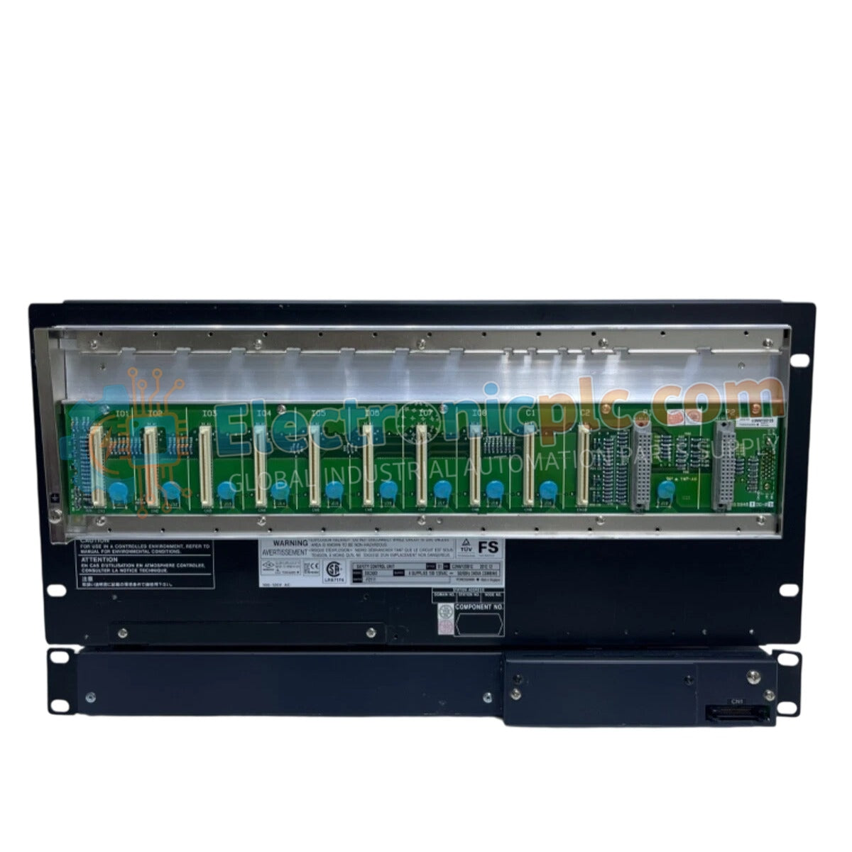
Configured for high-speed I/O communication and power distribution in N-IO system architectures, the YOKOGAWA S2BN1D-11130 (S2BN1D-11130 Network Interface Unit) provides direct physical signal processing and bus coupling. This hardware component serves as the communication gateway utilized to execute N-ESB bus data exchange between Safety Control Units and field I/O modules.
| Parameter | Specification |
|---|---|
| Model | S2BN1D-11130 |
| Brand | YOKOGAWA |
| Origin | Subject to factory marking |
| Weight | Not specified |
| Dimensions | Not specified |
| Operating Temp | Industrial standard range |
| Power Consumption | Not specified |
| Input Voltage | 100-240 VAC (50/60 Hz) or 24 VDC |
| Output Power | 24 VDC |
| I/O Capacity | Up to 6 units |
| Interface | N-ESB Bus |
| Isolation | 1500 VAC (1 min) |
The S2BN1D-11130 facilitates high-integrity data flow within N-IO networks, functioning as an intermediary for both signal pathing and voltage regulation. The unit manages the N-ESB bus, which enables deterministic communication required for safety instrumented system (SIS) applications. By providing isolated 24 VDC output power to connected I/O units, the interface unit ensures that localized power fluctuations do not propagate through the safety bus. The integration of galvanic isolation is a critical feature, preventing electrical noise from the field wiring from compromising the primary control bus.
Q: What is the purpose of the integrated micro-USB maintenance port?
A: The micro-USB port provides a dedicated interface for local commissioning, node number assignment, and diagnostic data extraction. It is intended for use with authorized configuration software during system startup or troubleshooting.
Q: Can the S2BN1D-11130 be mounted horizontally?
A: No. The installation guidelines strictly require vertical mounting (DIN rail or wall) to ensure proper heat dissipation and adherence to the device's thermal convection profiles. Horizontal mounting may lead to premature component degradation.


