سلة التسوق الخاصة بي
0 عنصرًا
قطع غيار أصلية للأتمتة | توصيل سريع عالمي | ضمان لمدة 12 شهرًا — [احصل على عرض سعر]

The YOKOGAWA SA53900, also cataloged as the SA-539-00 System Fault Alarm Module, operates as a dedicated hardware component for monitoring and annunciating system-level diagnostic errors within distributed control and PLC...
التوافر: في الأوراق المالية
توصيل موثوق به في جميع أنحاء العالم
ضمان استرداد الأموال خلال 30 يومًا
هل تحتاج إلى مزيد من التفاصيل؟ اقرأ سياسة الشحن وسياسة الاسترداد الكاملة.
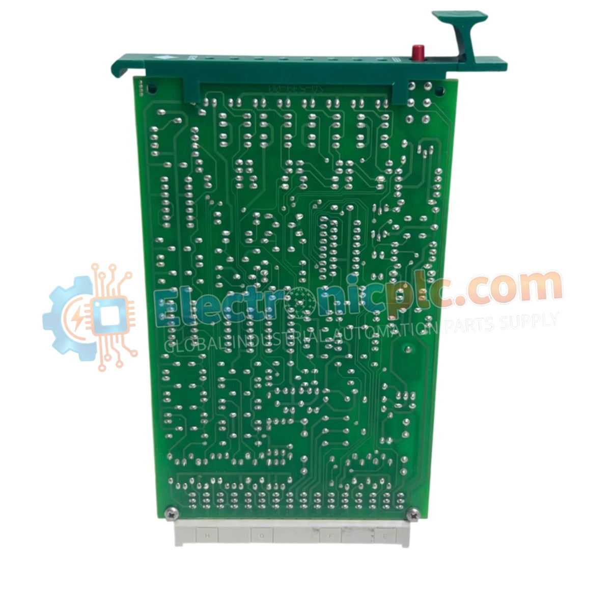

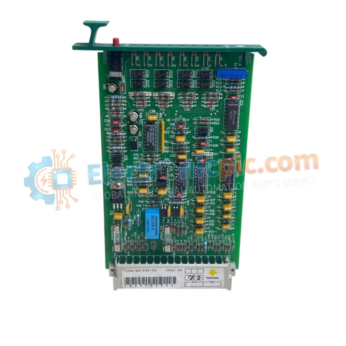
The YOKOGAWA SA53900, also cataloged as the SA-539-00 System Fault Alarm Module, operates as a dedicated hardware component for monitoring and annunciating system-level diagnostic errors within distributed control and PLC network architectures.
| Parameter | Specification |
|---|---|
| Model | SA53900 (SA-539-00) |
| Brand | YOKOGAWA |
| Origin | Japan |
| Weight | 0.11 kg (0.24 lbs) |
| Dimensions | Standard Yokogawa module form factor |
| Operating Temp | 0 deg C to 60 deg C |
| Power Consumption | 24 VDC nominal |
| Channels | 1 main channel with 8 sub-alarm inputs |
| Interface | LED status annunciation |
The SA53900 module is engineered to provide immediate visual and electrical feedback regarding system health. By integrating 8 sub-alarm inputs into a single managed channel, the module reduces the complexity of cabinet-level wiring while ensuring that critical faults are registered by the control system logic. The inclusion of front-panel LED indicators is required for rapid diagnostic verification by field maintenance personnel, allowing for immediate identification of fault conditions without needing to access the control system software.
Q: Does the SA53900 require external wiring for the 8 sub-alarm inputs?
A: Yes. Each sub-alarm input must be wired from the corresponding system component (e.g., power supply fault relays or chassis temperature sensors) to the module terminals to facilitate centralized fault monitoring.
Q: Is the SA53900 compatible with older Yokogawa control systems?
A: The module is designed for legacy system architectures. Ensure that the backplane voltage and communication protocols are compatible with the specific revision of the control rack before installation.


