سلة التسوق الخاصة بي
0 عنصرًا
قطع غيار أصلية للأتمتة | توصيل سريع عالمي | ضمان لمدة 12 شهرًا — [احصل على عرض سعر]

The Yokogawa SB401-10 S1 (SB401-10 S1 ESB Bus Interface Slave Module) operates as a dedicated hardware component for managing I/O communication between field control stations and remote slave nodes within...
التوافر: الكمية المتبقية: 99
توصيل موثوق به في جميع أنحاء العالم
ضمان استرداد الأموال خلال 30 يومًا
هل تحتاج إلى مزيد من التفاصيل؟ اقرأ سياسة الشحن وسياسة الاسترداد الكاملة.
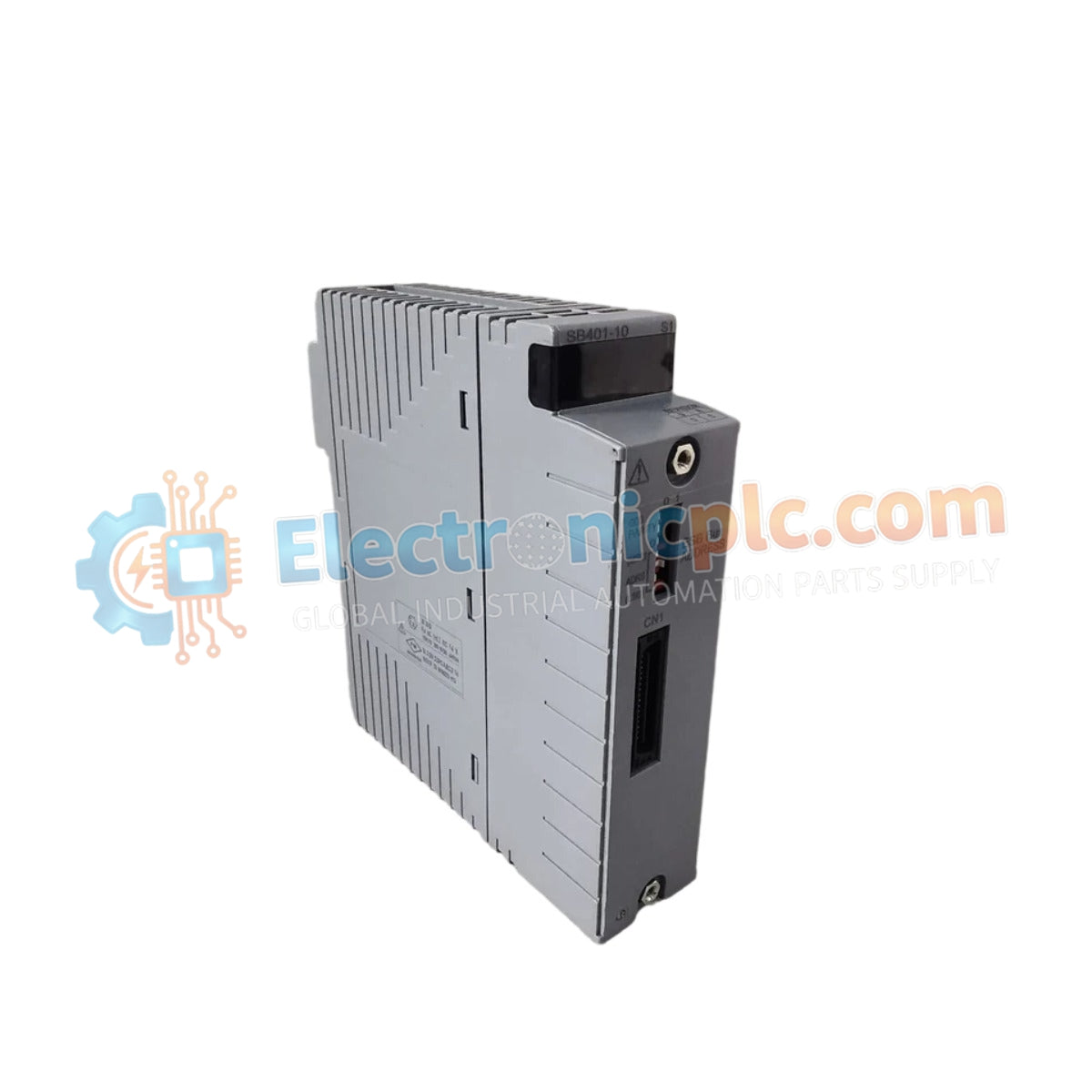

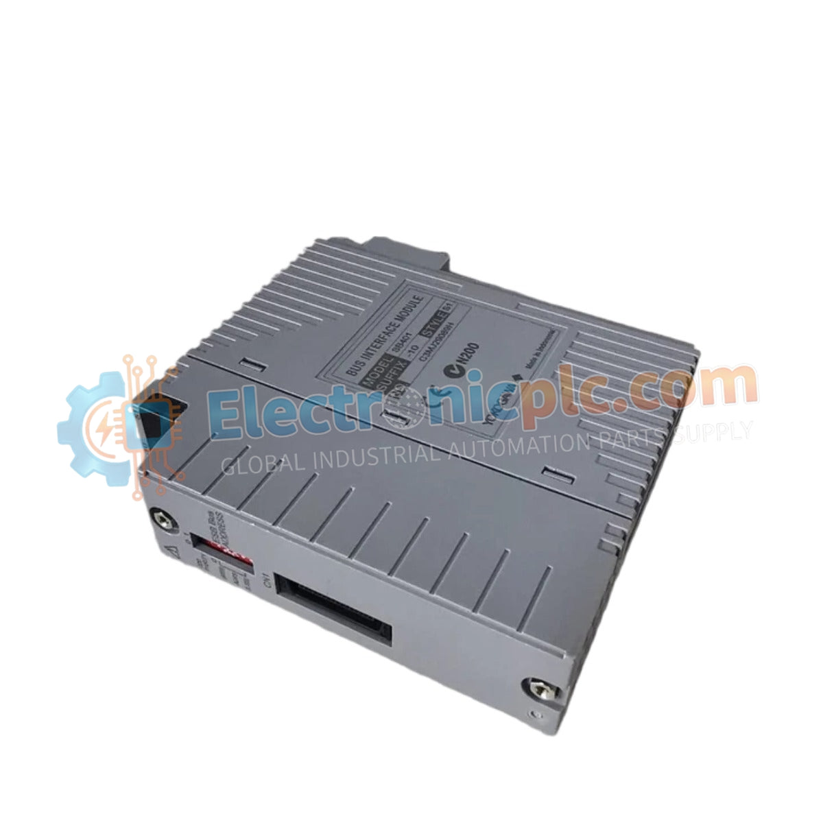
The Yokogawa SB401-10 S1 (SB401-10 S1 ESB Bus Interface Slave Module) operates as a dedicated hardware component for managing I/O communication between field control stations and remote slave nodes within distributed control systems. This module serves as the primary interface utilized to execute data synchronization and command routing across the Extended Standard Bus (ESB) architecture in upgraded Yokogawa CENTUM platforms.
The SB401-10 S1 designation identifies a hardware revision specifically optimized for enhanced signal processing on the ESB bus. The "S1" suffix indicates an iteration featuring refined backplane communication logic, providing improved compatibility with newer control station firmware compared to the base SB401-10 unit.
| Parameter | Specification |
|---|---|
| Model | SB401-10 S1 |
| Brand | Yokogawa |
| Origin | Japan |
| Weight | 0.3 kg |
| Dimensions | 3.2 cm x 10.7 cm x 13 cm |
| Operating Temp | 0 to 60 deg C |
| Power Consumption | 4 W (typical) |
| Interface Type | ESB Bus Slave |
The SB401-10 S1 integrates into the DCS architecture to provide deterministic communication between the control processor and remote I/O subsystems. It utilizes channel-to-channel isolation to decouple the ESB bus from field-side electrical noise, preventing ground potential differences from affecting the integrity of the data stream. The module supports robust bus timing synchronization, ensuring that high-speed I/O updates are captured without latency, thus maintaining accurate loop control across the distributed network.
Q: Is the SB401-10 S1 backwards compatible with standard SB401-10 installations?
A: In most CENTUM VP configurations, the S1 revision is a functional replacement; however, confirm that the system engineering station firmware supports the S1 hardware revision before deployment.
Q: Does this module require specific bus termination settings?
A: Yes, proper bus termination is mandatory at the physical end of the ESB bus segment to prevent signal reflections and ensure network data stability.


