سلة التسوق الخاصة بي
0 عنصرًا
قطع غيار أصلية للأتمتة | توصيل سريع عالمي | ضمان لمدة 12 شهرًا — [احصل على عرض سعر]

The Yokogawa SB401-11 (SB401-11 ESB Bus Interface Slave Module) operates as a dedicated hardware component for managing I/O communication between field control stations and remote slave nodes within distributed control...
التوافر: الكمية المتبقية: 99
توصيل موثوق به في جميع أنحاء العالم
ضمان استرداد الأموال خلال 30 يومًا
هل تحتاج إلى مزيد من التفاصيل؟ اقرأ سياسة الشحن وسياسة الاسترداد الكاملة.


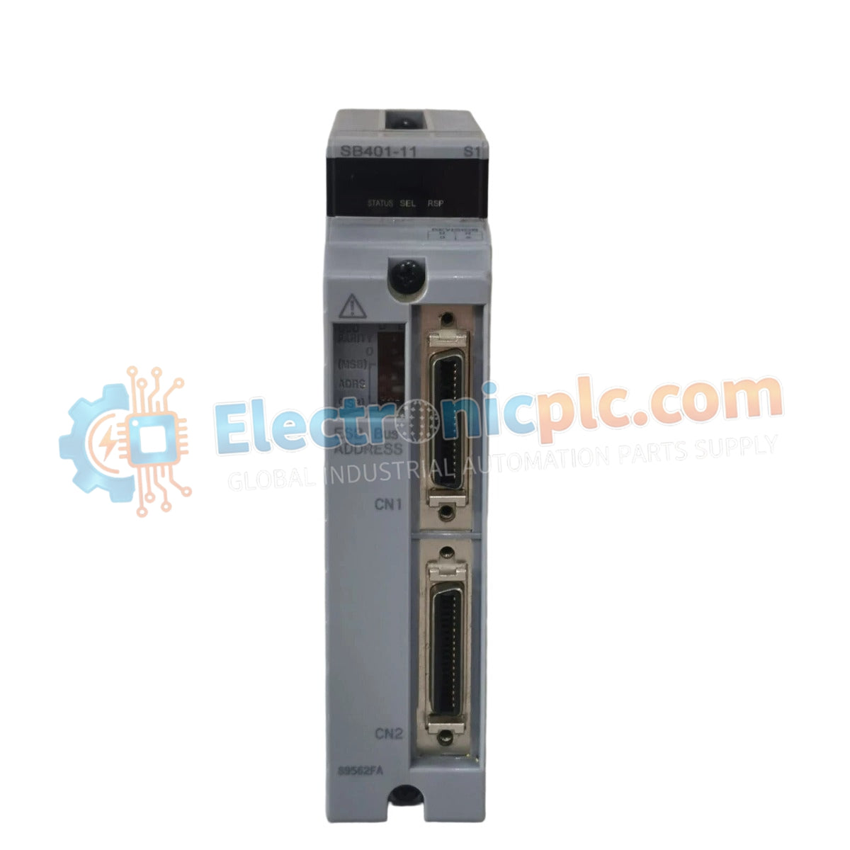
The Yokogawa SB401-11 (SB401-11 ESB Bus Interface Slave Module) operates as a dedicated hardware component for managing I/O communication between field control stations and remote slave nodes within distributed control systems. This module serves as the primary interface utilized to execute data synchronization and command routing across the Extended Standard Bus (ESB) architecture in Yokogawa CENTUM platforms, facilitating connectivity for dual-redundant bus configurations.
| Parameter | Specification |
|---|---|
| Model | SB401-11 |
| Brand | Yokogawa |
| Origin | Japan |
| Weight | 0.5 kg |
| Dimensions | 2.5 cm x 12.7 cm x 12.7 cm |
| Operating Temp | 0 to 60 deg C |
| Power Consumption | 4 W (typical) |
| Interface Type | ESB Bus Slave (Single-Port) |
The SB401-11 integrates into the DCS architecture to provide deterministic communication between the control processor and remote I/O subsystems. Designed for dual-redundant ESB bus environments, the module supports continuous data availability by bridging the control station to auxiliary nodes. It utilizes channel-to-channel isolation to decouple the ESB bus from field-side electrical noise, preventing ground potential differences from affecting the integrity of the data stream. The module supports robust bus timing synchronization, ensuring that high-speed I/O updates are captured without latency, thus maintaining accurate loop control across the distributed network.
Q: Is the SB401-11 compatible with dual-redundant ESB bus configurations?
A: Yes, the SB401-11 is specifically engineered to function within dual-redundant ESB bus architectures, providing the necessary interface for high-availability communication between the FCU and slave nodes.
Q: Does this module require manual bus termination during installation?
A: Proper bus termination is critical for ESB network stability; users must ensure the final slave node in the bus segment is correctly terminated according to the system installation manual to prevent signal reflections.


