انتقل إلى معلومات المنتج
1 ل 3

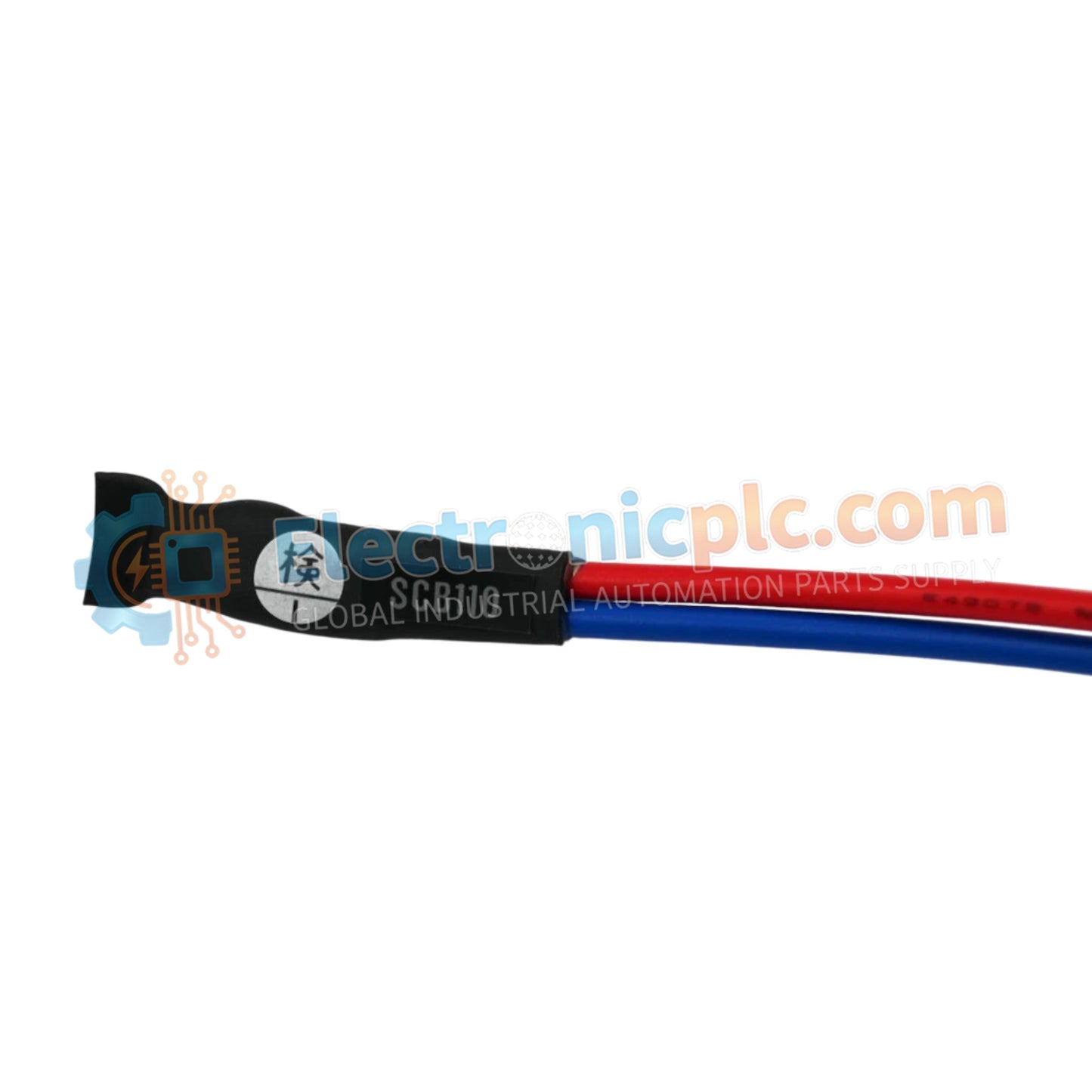
SCB110 Wiring Check Adapter YOKOGAWA

SCB110 Wiring Check Adapter YOKOGAWA

Configured for diagnostic validation in digital input instrumentation loops, the YOKOGAWA SCB110-S0 (SCB110-S0 Wiring Check Adapter) provides direct physical monitoring and verification of digital signal circuits across PLC and DCS platforms.

...
20 يشاهد الناس هذا الآن

التوافرفي الأوراق المالية

رمز المنتج: SCB110
بائع: Yokogawa
Related Series:

الشحن والإرجاع

توصيل موثوق به في جميع أنحاء العالم

  • شركات الشحن: يتم الشحن عبر DHL أو FedEx أو UPS أو USPS .
  • الشحن: تتم معالجة الطلبات خلال يوم عمل واحد إلى يومين، ويتم شحنها خلال 3 إلى 5 أيام عمل .
  • التتبع: يتم توفير تفاصيل التتبع الكاملة عبر البريد الإلكتروني عند الشحن.

ضمان استرداد الأموال خلال 30 يومًا

  • الضمان: فترة إرجاع لمدة 30 يومًا للمنتجات المتوفرة في المخزون والمغلفة من المصنع.
  • الشروط: يجب أن تكون المنتجات غير مفتوحة وغير مستخدمة وفي عبوتها الأصلية.
  • الأصالة: نضمن أن تكون الأجهزة أصلية 100% .

هل تحتاج إلى مزيد من التفاصيل؟ اقرأ سياسة الشحن وسياسة الاسترداد الكاملة.

الأصالة والضمان

  • ضمان أصلي: نحن نوفر فقط قطع غيار أصلية 100%، جديدة تمامًا، ومغلقة من المصنع .
  • تغطية كاملة: كل مكون مدعوم بضمان شامل لمدة 12 شهرًا من تاريخ الشراء.
  • إمكانية التتبع: جميع المنتجات تأتي مع وثائق المصنع الأصلية والملحقات اللازمة للامتثال الكامل للمعايير الصناعية.

الدعم الفني والتوريد

  • مساعدة الخبراء: يقدم فريقنا الفني استشارات مجانية لمساعدتك في التحقق من التوافق مع أنظمة DCS و PLC.
  • مصادر القطع النادرة: متخصصون في المكونات القديمة والتي يصعب العثور عليها من Allen-Bradley و Siemens و ABB و HIMA وغيرها.
  • للاستفسارات المتعلقة بالكميات الكبيرة: تواصلوا معنا على pambo@5gplc.com للحصول على أسعار الكميات الكبيرة أو عروض أسعار المشاريع المخصصة.
عرض تفاصيل المنتج الكاملة

Configured for diagnostic validation in digital input instrumentation loops, the YOKOGAWA SCB110-S0 (SCB110-S0 Wiring Check Adapter) provides direct physical monitoring and verification of digital signal circuits across PLC and DCS platforms.

Hardware Specifications

Parameter Specification
Model SCB110-S0
Brand YOKOGAWA
Origin Japan
Weight 0.5kg
Dimensions Standard terminal interface form factor
Operating Temp Not specified
Power Consumption Passive (Loop powered)
Input Type Digital Input (DI) verification
Mounting Terminal block interface
Protection Standard industrial enclosure

Process Control Diagnostic Connectivity

The SCB110-S0 is engineered to facilitate rapid verification of field wiring without requiring live signals from field transmitters. By acting as a diagnostic bridge, the adapter allows technicians to simulate input states, ensuring that channel-to-channel isolation and signal path integrity are confirmed prior to full system commissioning. This physical verification capability is essential for identifying wiring faults, such as open circuits or short-to-ground conditions, within complex digital I/O architectures.

Frequently Asked Questions

Q: Does the SCB110-S0 require external power for wiring verification?

A: No, the adapter is a passive device designed to interface with the existing I/O module power supply. It utilizes the loop current to facilitate state verification during the testing phase.

Q: Can this adapter be left in the circuit during normal operation?

A: The SCB110-S0 is intended for diagnostic and commissioning purposes. It should be removed from the signal path once wiring verification is complete to ensure the I/O module operates within its design parameters.

Field Installation Guidelines

  • Ensure the system is in a controlled state prior to connecting the adapter to prevent accidental triggering of alarm logic in the DCS or PLC.
  • Verify that the terminal interface is free of debris or oxidation to maintain a low-resistance connection during diagnostic checks.
  • Secure the adapter firmly to the terminal block to prevent intermittent contact, which could generate false digital transitions.
  • Follow standard industrial safety practices when verifying loops, including the use of verified multimeters to confirm voltage levels before and after adapter insertion.
  • Maintain clear documentation of verified signal paths to ensure all diagnostic bridges are removed before final system handover.