سلة التسوق الخاصة بي
0 عنصرًا
قطع غيار أصلية للأتمتة | توصيل سريع عالمي | ضمان لمدة 12 شهرًا — [احصل على عرض سعر]

The YOKOGAWA KS2-50*B, also cataloged as the KS2-50 Signal Cable, operates as a dedicated hardware component for the transmission of multi-channel analog and digital signals between field devices and control...
التوافر: في الأوراق المالية
توصيل موثوق به في جميع أنحاء العالم
ضمان استرداد الأموال خلال 30 يومًا
هل تحتاج إلى مزيد من التفاصيل؟ اقرأ سياسة الشحن وسياسة الاسترداد الكاملة.
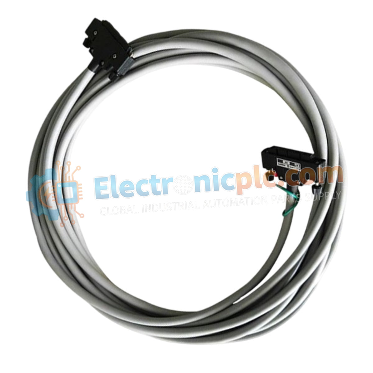
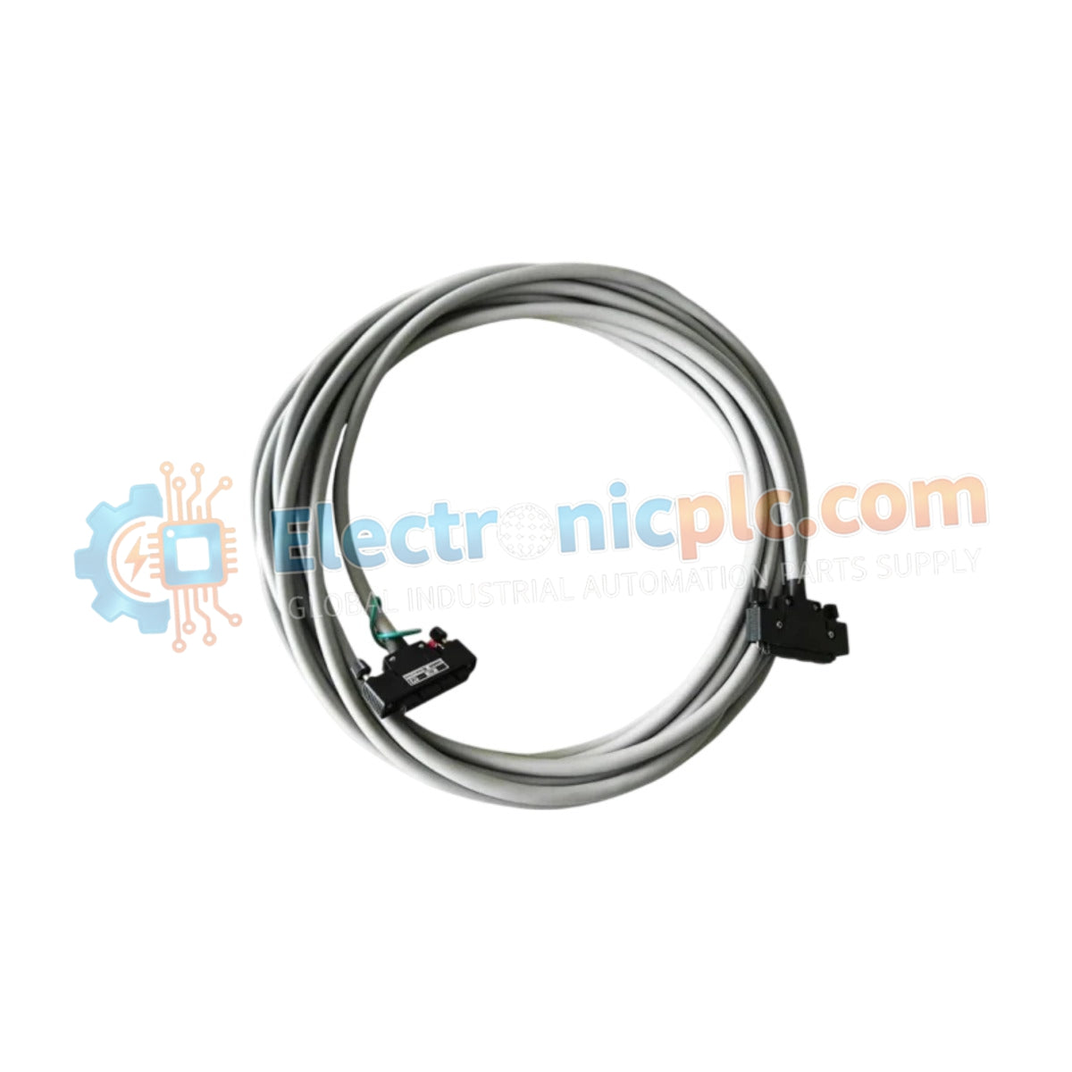
The YOKOGAWA KS2-50*B, also cataloged as the KS2-50 Signal Cable, operates as a dedicated hardware component for the transmission of multi-channel analog and digital signals between field devices and control system I/O modules.
| Parameter | Specification |
|---|---|
| Model | KS2-50*B |
| Brand | YOKOGAWA |
| Origin | Japan |
| Weight | 0.5kg |
| Dimensions | 20-pair cable geometry |
| Operating Temp | -20 deg C to 70 deg C |
| Power Consumption | Passive (0 W) |
| Connector Type | 40-pin connectors (both ends) |
| Cable Type | 20-pair shielded |
The KS2-50*B cable is engineered to maintain high signal fidelity for 4-20 mA HART loop protocol loops and discrete digital I/O signals. Within Yokogawa DCS architectures, the integration of 20-pair shielded cabling is required to prevent crosstalk and electromagnetic interference (EMI) between adjacent channels. The use of high-density 40-pin connectors facilitates rapid deployment while ensuring individual pair shielding, which is necessary to maintain the signal-to-noise ratio required for precise process data transmission.
Q: Can the KS2-50*B cable be shortened or modified in the field?
A: Field modification of the 40-pin connectors is not recommended. The factory-molded connectors ensure proper impedance and contact integrity. Modifying the cable assembly may compromise the shielding continuity and lead to signal attenuation or ground loop issues.
Q: Is this cable suitable for use in high-vibration environments?
A: The cable is designed for standard industrial control cabinet routing. If installed in areas subject to mechanical vibration, ensure the cable is properly secured with cable ties to prevent fatigue at the 40-pin connector interfaces.


