انتقل إلى معلومات المنتج
1 ل 3

SNB10D-215/CU2N YOKOGAWA Safety Node Unit | New & Original Stock

SNB10D-215/CU2N YOKOGAWA Safety Node Unit | New & Original Stock

Configured for distributed I/O management in safety-instrumented systems, the YOKOGAWA SNB10D-215/CU2N (SNB10D Safety Node Unit) provides direct physical and electrical execution of ESB bus signal routing and I/O module communication...

15 يشاهد الناس هذا الآن

التوافرالكمية المتبقية: 99

رمز المنتج: SNB10D-215/CU2N
بائع: Yokogawa
Related Series:

الشحن والإرجاع

توصيل موثوق به في جميع أنحاء العالم

  • شركات الشحن: يتم الشحن عبر DHL أو FedEx أو UPS أو USPS .
  • الشحن: تتم معالجة الطلبات خلال يوم عمل واحد إلى يومين، ويتم شحنها خلال 3 إلى 5 أيام عمل .
  • التتبع: يتم توفير تفاصيل التتبع الكاملة عبر البريد الإلكتروني عند الشحن.

ضمان استرداد الأموال خلال 30 يومًا

  • الضمان: فترة إرجاع لمدة 30 يومًا للمنتجات المتوفرة في المخزون والمغلفة من المصنع.
  • الشروط: يجب أن تكون المنتجات غير مفتوحة وغير مستخدمة وفي عبوتها الأصلية.
  • الأصالة: نضمن أن تكون الأجهزة أصلية 100% .

هل تحتاج إلى مزيد من التفاصيل؟ اقرأ سياسة الشحن وسياسة الاسترداد الكاملة.
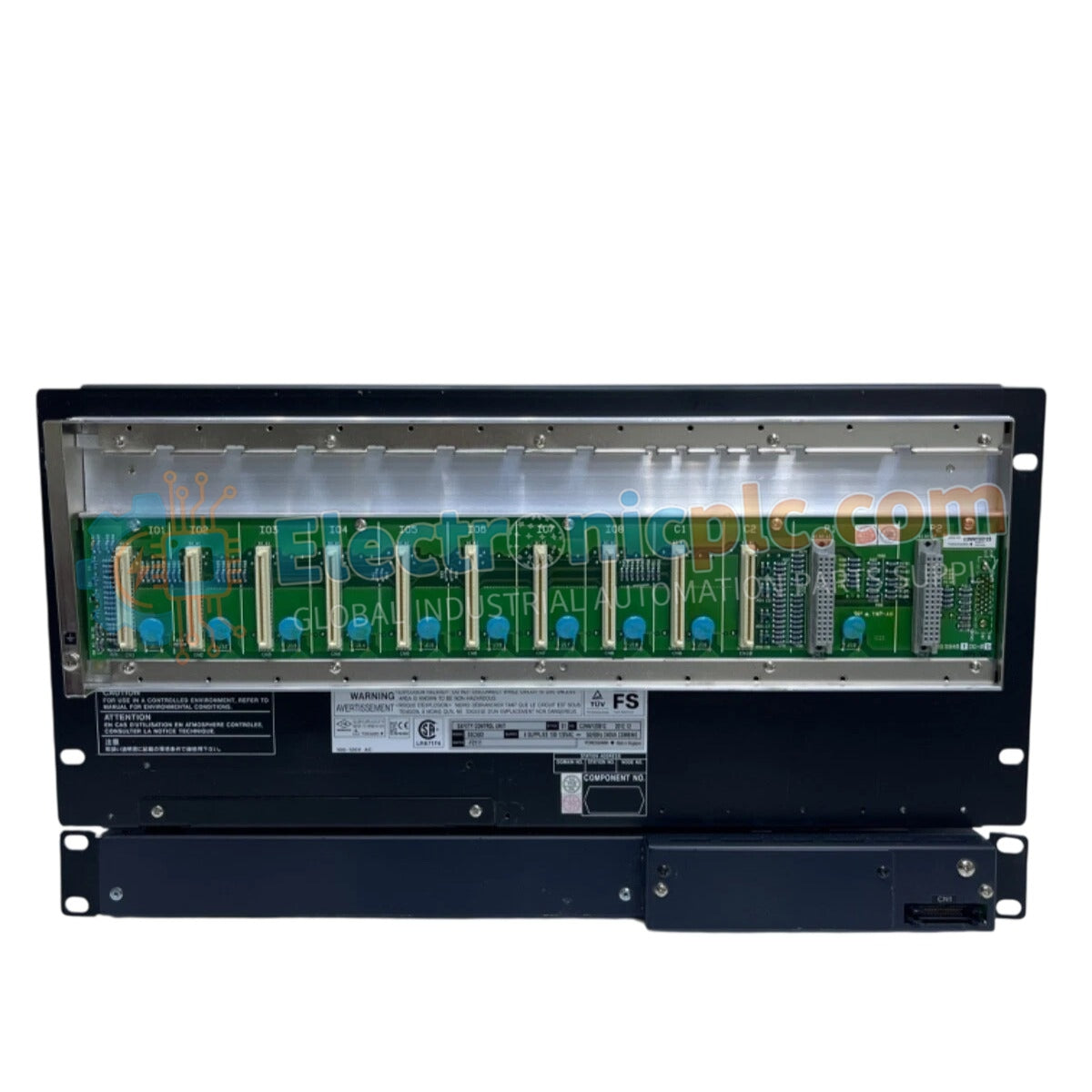
الأصالة والضمان

  • ضمان أصلي: نحن نوفر فقط قطع غيار أصلية 100%، جديدة تمامًا، ومغلقة من المصنع .
  • تغطية كاملة: كل مكون مدعوم بضمان شامل لمدة 12 شهرًا من تاريخ الشراء.
  • إمكانية التتبع: جميع المنتجات تأتي مع وثائق المصنع الأصلية والملحقات اللازمة للامتثال الكامل للمعايير الصناعية.

الدعم الفني والتوريد

  • مساعدة الخبراء: يقدم فريقنا الفني استشارات مجانية لمساعدتك في التحقق من التوافق مع أنظمة DCS و PLC.
  • مصادر القطع النادرة: متخصصون في المكونات القديمة والتي يصعب العثور عليها من Allen-Bradley و Siemens و ABB و HIMA وغيرها.
  • للاستفسارات المتعلقة بالكميات الكبيرة: تواصلوا معنا على pambo@5gplc.com للحصول على أسعار الكميات الكبيرة أو عروض أسعار المشاريع المخصصة.
عرض تفاصيل المنتج الكاملة

Configured for distributed I/O management in safety-instrumented systems, the YOKOGAWA SNB10D-215/CU2N (SNB10D Safety Node Unit) provides direct physical and electrical execution of ESB bus signal routing and I/O module communication within the CENTUM VP and ProSafe-RS control environments.

Suffix Breakdown & Model Matrix

The SNB10D series utilizes a modular suffix code system to define hardware configuration and electrical standards:

  • Model SNB10D: ESB Bus Node Unit (Safety version).
  • Suffix 215: Denotes standard hardware revision and chassis configuration.
  • Suffix /CU2N: Specifies the specific electrical interface and environmental protection requirements for safety-critical applications.

Hardware Specifications

Parameter Specification
Model SNB10D-215/CU2N
Brand YOKOGAWA
Origin Japan
Weight 5.52 kg
Dimensions 18.4 x 15 x 3 cm
Operating Temp Standard industrial range
Power Consumption Subject to node load
Bus Interface ESB Bus
Function Safety Node communication

SIS and Galvanic Isolation Characteristics

The SNB10D-215/CU2N is engineered to maintain high-integrity communication within safety-instrumented systems. The internal architecture facilitates galvanic isolation between the ESB bus interface and the local I/O backplane, effectively mitigating ground loops and common-mode noise that could trigger spurious trips. This unit serves as the physical anchor for safety I/O modules, ensuring that fail-safe state execution signals are transmitted with deterministic latency to the field control unit. The unit is optimized for high-density I/O configurations while maintaining strict adherence to safety bus impedance specifications to prevent signal corruption.

Frequently Asked Questions

Q: Does the SNB10D-215/CU2N support hot-swapping of safety I/O modules?

A: Yes, the node unit is designed to allow for the replacement of individual I/O modules during operation, provided the specific safety integrity level (SIL) documentation and local site protocols permit online maintenance.

Q: How does the /CU2N suffix affect integration with existing nodes?

A: The /CU2N suffix defines specific interface parameters and cooling/protection configurations. It is fully compatible with standard ESB bus backplanes, but verification of the local node rack configuration is required before installation.

Field Installation Guidelines

  1. Ensure the safety node power is completely disconnected before mounting the unit into the cabinet chassis.
  2. Align the unit within the cabinet rack and secure it using the provided fasteners to ensure sufficient mechanical stability against vibration.
  3. Connect the ESB bus cables to the node interface ports; ensure the cables are properly routed and protected from sharp edges.
  4. Verify that the shield drain wires are grounded to the designated cabinet grounding bar to maintain the integrity of the safety signal path.
  5. After physical installation, perform a status check via the control system engineering station to confirm the node is recognized and the communication link is healthy.