سلة التسوق الخاصة بي
0 عنصرًا
قطع غيار أصلية للأتمتة | توصيل سريع عالمي | ضمان لمدة 12 شهرًا — [احصل على عرض سعر]

تم تكوينه لنقل الإشارات لمسافات طويلة ضمن شبكات التحكم يوكوجاوا، توفر وحدة YOKOGAWA SNT401-53 S1 (وحدة مكرر ناقل ESB البصري SNT401-53 S1) تحويل الإشارة البصرية للناقل المتزامن الموسع (ESB). يسمح...
التوافر: الكمية المتبقية: 99
توصيل موثوق به في جميع أنحاء العالم
ضمان استرداد الأموال خلال 30 يومًا
هل تحتاج إلى مزيد من التفاصيل؟ اقرأ سياسة الشحن وسياسة الاسترداد الكاملة.

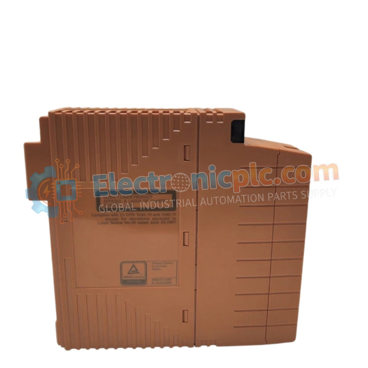
تم تكوينه لنقل الإشارات لمسافات طويلة ضمن شبكات التحكم يوكوجاوا، توفر وحدة YOKOGAWA SNT401-53 S1 (وحدة مكرر ناقل ESB البصري SNT401-53 S1) تحويل الإشارة البصرية للناقل المتزامن الموسع (ESB). يسمح مكون الأجهزة هذا بربط عقد الإدخال/الإخراج على مسافات مادية أطول مما تسمح به الكابلات النحاسية القياسية، باستخدام وسائط الألياف البصرية للحفاظ على تبادل البيانات عالي السرعة والتحديد عبر مناطق العملية الموزعة.
| المعلمة | المواصفات |
|---|---|
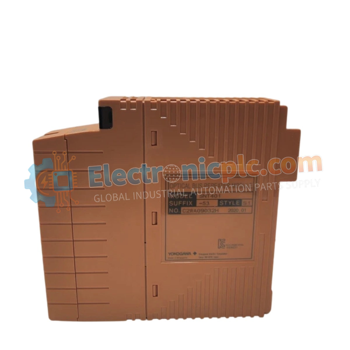
| النموذج | SNT401-53 S1 |
| العلامة التجارية | يوكوجاوا |
| الأصل | اليابان |
| الوزن | 0.3 كجم |
| الأبعاد | 2.2 سم × 12.4 سم × 12.6 سم |
| درجة حرارة التشغيل | النطاق المحيطي الصناعي القياسي |
| استهلاك الطاقة | مصدر طاقة لوحة خلفية DCS الاسمي |
| الوظيفة | تحويل الإشارة البصرية لناقل ESB |
تقوم وحدة SNT401-53 S1 بتحويل إشارات ESB الكهربائية إلى نبضات بصرية، مما يتيح نقل بيانات موثوقًا بين وحدة التحكم الميدانية (FCU) وعقد الإدخال/الإخراج البعيدة. يوفر النقل البصري مناعة متأصلة ضد التداخل الكهرومغناطيسي (EMI) وتداخل التردد اللاسلكي (RFI)، مما يجعله الحل الأمثل للبيئات ذات الضوضاء الكهربائية العالية، مثل تلك القريبة من المفاتيح الكهربائية عالية الجهد أو محركات المحركات الثقيلة.
س: هل يمكن استخدام هذه الوحدة لربط عقد الإدخال/الإخراج على مسافات طويلة؟
ج: تم تصميم SNT401 لتوسيع نطاق ناقل ESB باستخدام الألياف البصرية. عند تصميم الطوبولوجيا، تأكد من أن الطول الكلي للألياف وعدد المكررات لا يتجاوز حدود التوقيت وتوهين الإشارة المحددة في دليل تخطيط نظام Yokogawa.
س: ما نوع موصل الألياف البصرية المطلوب؟
ج: تأكد من تطابق الواجهة مع مواصفات أجهزة SNT401-53 المحددة. تُستخدم واجهات الألياف الصناعية القياسية عادةً؛ تحقق من توافق قطر قلب الألياف (مثل متعدد الوضع مقابل أحادي الوضع) قبل شراء الكابل.


