سلة التسوق الخاصة بي
0 عنصرًا
قطع غيار أصلية للأتمتة | توصيل سريع عالمي | ضمان لمدة 12 شهرًا — [احصل على عرض سعر]

The YOKOGAWA SPW484-53, also cataloged as the SPW484 Power Supply Module, operates as a dedicated hardware component for power regulation within industrial automation systems. This module executes the conversion of...
التوافر: الكمية المتبقية: 99
توصيل موثوق به في جميع أنحاء العالم
ضمان استرداد الأموال خلال 30 يومًا
هل تحتاج إلى مزيد من التفاصيل؟ اقرأ سياسة الشحن وسياسة الاسترداد الكاملة.


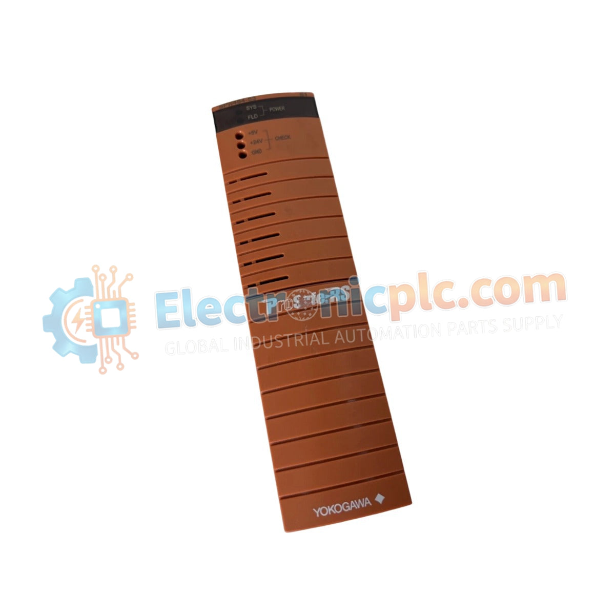
The YOKOGAWA SPW484-53, also cataloged as the SPW484 Power Supply Module, operates as a dedicated hardware component for power regulation within industrial automation systems. This module executes the conversion of a 24 VDC input into regulated multi-rail DC outputs, providing the electrical potential required for Field Control Units, remote I/O modules, and associated control devices.
| Parameter | Specification |
|---|---|
| Model | SPW484-53 |
| Brand | Yokogawa |
| Origin | Japan |
| Weight | 0.9 kg |
| Dimensions | 17.8 cm x 19.1 cm x 19.7 cm |
| Input Voltage | 24 VDC |
| Output Voltages | 5 VDC, 3.3 VDC, 24 VDC |
| Output Current | 5 VDC: 2 A; 3.3 VDC: 1 A; 24 VDC: 2 A |
| Operating Temp | -20 deg C to +60 deg C |
| Efficiency | Up to 85% |
The SPW484-53 maintains consistent voltage rails across multiple output channels, which is necessary for the integrity of control bus communication and field instrument stability. The unit features channel-to-channel isolation to prevent the propagation of common-mode electrical noise and ground loops between output rails. Additionally, the internal thermal management system facilitates stable power delivery across the specified -20 deg C to +60 deg C range, ensuring operational continuity in harsh industrial environments.
Q: Can the SPW484-53 be used to power devices with different voltage requirements simultaneously?
A: Yes, the module provides isolated 5 VDC, 3.3 VDC, and 24 VDC rails, allowing it to supply power to mixed-voltage control components such as logic processors and remote I/O sensors concurrently.
Q: What are the risks of operating the module near its maximum temperature limit of +60 deg C?
A: While rated for operation up to +60 deg C, continuous operation at the upper temperature limit may induce thermal stress on internal electrolytic capacitors. Ensure optimal clearance around the module to allow for natural convection to maximize the longevity of the power conversion stages.


