سلة التسوق الخاصة بي
0 عنصرًا
قطع غيار أصلية للأتمتة | توصيل سريع عالمي | ضمان لمدة 12 شهرًا — [احصل على عرض سعر]

The Yokogawa SSB401-13 (SSB401-13 Optical ESB Bus Repeater Module) operates as a dedicated hardware component for extending the physical reach of the Extended Standard Bus (ESB) within distributed control systems....
التوافر: الكمية المتبقية: 99
توصيل موثوق به في جميع أنحاء العالم
ضمان استرداد الأموال خلال 30 يومًا
هل تحتاج إلى مزيد من التفاصيل؟ اقرأ سياسة الشحن وسياسة الاسترداد الكاملة.


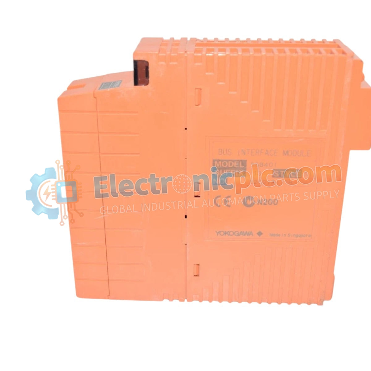
The Yokogawa SSB401-13 (SSB401-13 Optical ESB Bus Repeater Module) operates as a dedicated hardware component for extending the physical reach of the Extended Standard Bus (ESB) within distributed control systems. This module serves as the primary interface utilized to execute optical signal conversion and data transmission across high-EMI industrial environments, ensuring reliable communication between remote I/O nodes and the control processor.
| Parameter | Specification |
|---|---|
| Model | SSB401-13 |
| Brand | Yokogawa |
| Origin | Japan |
| Weight | 0.9 kg |
| Dimensions | 5.1 cm x 20.3 cm x 14.6 cm |
| Operating Temp | 0 to 60 deg C |
| Power Consumption | 6 W (typical) |
| Interface Type | Optical ESB Bus |
The SSB401-13 integrates into the DCS architecture to provide robust signal isolation between control station segments. By converting electrical bus signals into optical pulses, the module effectively eliminates ground potential differences and common-mode noise issues that occur across long-distance copper cabling. This design ensures deterministic communication latency, which is required for high-speed I/O processing in large-scale CENTUM control networks. The module also supports firmware flash compatibility, allowing for updates to maintain timing synchronization as system configurations evolve.
Q: Does the optical signal conversion introduce significant latency to the ESB bus?
A: The SSB401-13 is engineered for minimal propagation delay, ensuring that overall bus timing remains within the strict parameters defined for the CENTUM ESB architecture.
Q: Is this module capable of driving multimode optical fiber over long distances?
A: The module is designed for standard industrial fiber-optic link lengths; verify the specific optical power budget against the installed fiber plant before commissioning.


