سلة التسوق الخاصة بي
0 عنصرًا
قطع غيار أصلية للأتمتة | توصيل سريع عالمي | ضمان لمدة 12 شهرًا — [احصل على عرض سعر]

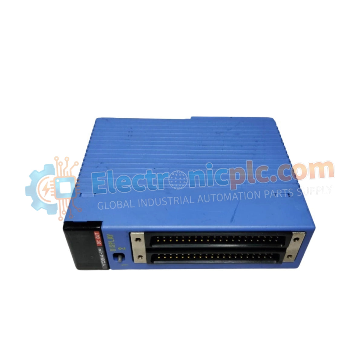
Configured for high-density digital signal switching in FA-M3 control networks, the Yokogawa F3YD64-1P/K2 (F3YD64-1P/K2 Transistor Output Module) provides direct electrical execution for 64-channel field device actuation via transistor sink-type outputs.
...التوافر: في الأوراق المالية
توصيل موثوق به في جميع أنحاء العالم
ضمان استرداد الأموال خلال 30 يومًا
هل تحتاج إلى مزيد من التفاصيل؟ اقرأ سياسة الشحن وسياسة الاسترداد الكاملة.


Configured for high-density digital signal switching in FA-M3 control networks, the Yokogawa F3YD64-1P/K2 (F3YD64-1P/K2 Transistor Output Module) provides direct electrical execution for 64-channel field device actuation via transistor sink-type outputs.
The F3YD64-1P/K2 defines a high-capacity output module within the FA-M3 architecture. The "/K2" designation signifies a specific terminal interface arrangement, facilitating streamlined wiring for multi-channel systems while maintaining the standard 64-point transistor output matrix.
| Parameter | Specification |
|---|---|
| Model | F3YD64-1P/K2 |
| Brand | Yokogawa |
| Origin | Japan |
| Weight | 0.3 kg |
| Dimensions | 2.89 cm (W) x 8.32 cm (D) x 10 cm (H) |
| Operating Temp | 0 to 55 deg C |
| Power Consumption | 275 mA (5 V DC) |
| Output Points | 64 |
| Load Voltage | 12 to 24 V DC |
| Output Current | 0.1 A per point |
The F3YD64-1P/K2 facilitates robust switching for industrial process control loops. The module architecture employs photocoupler isolation to ensure signal integrity and electrical safety, providing 1500 V AC withstanding voltage between external connection terminals and the internal logic circuitry.
The 8-point-per-common grouping enables precise segmentation of field power, allowing for individual control loops to maintain channel-to-channel isolation effectiveness. This prevents cumulative noise interference and protects the central processor from load-side transients in complex FA-M3 automation environments.
Q: Is this module compatible with inductive loads?
A: Yes, provided that a flyback diode is installed in parallel with the load. Since this is a transistor-based sink output module, back-EMF suppression is required to prevent permanent damage to the output transistors when switching solenoids, relays, or other inductive devices.
Q: Can the common lines be bridged for higher current capacity?
A: No. The common lines are physically segmented into 8-point groups to maintain internal thermal and current limits. Do not attempt to parallel outputs or commons to exceed the 0.4 A-per-common limit.


