انتقل إلى معلومات المنتج
1 ل 3

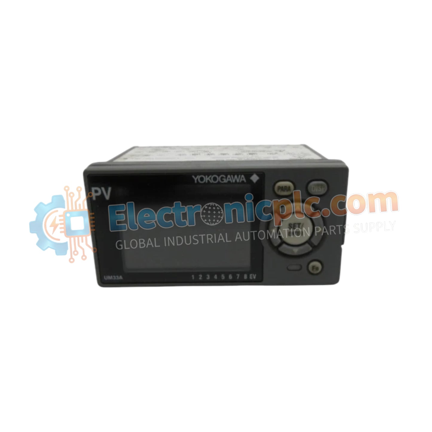
UM33A-000-11/LP Digital Indicator YOKOGAWA

UM33A-000-11/LP Digital Indicator YOKOGAWA

Configured for precision process monitoring and alarm signal management, the YOKOGAWA UM33A-000-11 (UM33A-000-11/LP Digital Indicator) provides direct physical signal processing for industrial instrumentation loops.

Suffix Breakdown & Model Matrix

    ...
29 يشاهد الناس هذا الآن

التوافرفي الأوراق المالية

رمز المنتج: UM33A-000-11/LP
بائع: Yokogawa
Related Series:

الشحن والإرجاع

توصيل موثوق به في جميع أنحاء العالم

  • شركات الشحن: يتم الشحن عبر DHL أو FedEx أو UPS أو USPS .
  • الشحن: تتم معالجة الطلبات خلال يوم عمل واحد إلى يومين، ويتم شحنها خلال 3 إلى 5 أيام عمل .
  • التتبع: يتم توفير تفاصيل التتبع الكاملة عبر البريد الإلكتروني عند الشحن.

ضمان استرداد الأموال خلال 30 يومًا

  • الضمان: فترة إرجاع لمدة 30 يومًا للمنتجات المتوفرة في المخزون والمغلفة من المصنع.
  • الشروط: يجب أن تكون المنتجات غير مفتوحة وغير مستخدمة وفي عبوتها الأصلية.
  • الأصالة: نضمن أن تكون الأجهزة أصلية 100% .

هل تحتاج إلى مزيد من التفاصيل؟ اقرأ سياسة الشحن وسياسة الاسترداد الكاملة.

الأصالة والضمان

  • ضمان أصلي: نحن نوفر فقط قطع غيار أصلية 100%، جديدة تمامًا، ومغلقة من المصنع .
  • تغطية كاملة: كل مكون مدعوم بضمان شامل لمدة 12 شهرًا من تاريخ الشراء.
  • إمكانية التتبع: جميع المنتجات تأتي مع وثائق المصنع الأصلية والملحقات اللازمة للامتثال الكامل للمعايير الصناعية.

الدعم الفني والتوريد

  • مساعدة الخبراء: يقدم فريقنا الفني استشارات مجانية لمساعدتك في التحقق من التوافق مع أنظمة DCS و PLC.
  • مصادر القطع النادرة: متخصصون في المكونات القديمة والتي يصعب العثور عليها من Allen-Bradley و Siemens و ABB و HIMA وغيرها.
  • للاستفسارات المتعلقة بالكميات الكبيرة: تواصلوا معنا على pambo@5gplc.com للحصول على أسعار الكميات الكبيرة أو عروض أسعار المشاريع المخصصة.
عرض تفاصيل المنتج الكاملة

Configured for precision process monitoring and alarm signal management, the YOKOGAWA UM33A-000-11 (UM33A-000-11/LP Digital Indicator) provides direct physical signal processing for industrial instrumentation loops.

Suffix Breakdown & Model Matrix

  • UM33A: Base model for 1/8 DIN digital indicator.
  • -000: Specifies standard hardware functionality without advanced network or custom logic blocks.
  • -11: Defines English default display language and black case color configuration.
  • -LP: Designates the integrated 24 VDC loop power supply option.

Hardware Specifications

Parameter Specification
Model UM33A-000-11/LP
Brand YOKOGAWA
Origin Japan
Weight 0.5 kg
Dimensions 9.6 cm x 4.8 cm x 6.5 cm
Panel Cutout 9.2 cm x 4.5 cm
Operating Temp Not specified
Power Consumption Not specified
Input Type 2-point no-voltage contact or transistor
Output Type 4-20 mA DC or 0-20 mA DC retransmission
Alarm Configuration 3 points (1a contact) + 1 point (1c contact)
Mounting Up to 30 deg above horizontal

Process Control Instrumentation Connectivity

The UM33A utilizes standard 4-20 mA HART loop protocol principles for retransmission, allowing seamless data forwarding to secondary DCS or PLC monitoring nodes. The device provides internal galvanic isolation between the signal input and the retransmission output to prevent ground loops. It features specific alarm logic execution capabilities, ensuring that process deviations are detected and signaled immediately through the independent 1a/1c relay contact architecture.

Frequently Asked Questions

Q: Can the UM33A be mounted in a vertical or downward-tilted orientation?

A: No, mounting is restricted to a maximum of 30 degrees above horizontal. Downward tilting is strictly prohibited to maintain proper heat dissipation and internal component longevity.

Q: How is the 24 VDC loop power supply utilized?

A: The /LP option provides dedicated power to field transmitters directly through the signal loop, eliminating the requirement for external power supplies for standard 4-20 mA loops.

Field Installation Guidelines

  • Verify that the panel cutout dimensions (9.2 cm x 4.5 cm) are exact; undersized cutouts may induce structural stress on the polycarbonate housing.
  • Use M3 screw terminals with square washers for all signal and power connections to ensure low-resistance, vibration-resistant contact.
  • Ensure no downward tilting is present during installation to prevent thermal accumulation within the 1/8 DIN housing.
  • Route signal cabling separately from high-voltage AC lines to mitigate electromagnetic induction, which can cause erratic alarm triggering.
  • Ground the instrument common as per local electrical safety standards to maintain the integrity of the galvanic isolation between input and retransmission stages.