انتقل إلى معلومات المنتج
1 ل 3

VI451-10 Yokogawa Communication Module | New & Original Stock

VI451-10 Yokogawa Communication Module | New & Original Stock

The Yokogawa VI451-10, also cataloged as the VI451-10 Communication Module, operates as a dedicated hardware component for facilitating data transmission and process synchronization within distributed control network architectures. This component...

15 يشاهد الناس هذا الآن

التوافرالكمية المتبقية: 99

رمز المنتج: VI451-10
بائع: Yokogawa
Related Series:

الشحن والإرجاع

توصيل موثوق به في جميع أنحاء العالم

  • شركات الشحن: يتم الشحن عبر DHL أو FedEx أو UPS أو USPS .
  • الشحن: تتم معالجة الطلبات خلال يوم عمل واحد إلى يومين، ويتم شحنها خلال 3 إلى 5 أيام عمل .
  • التتبع: يتم توفير تفاصيل التتبع الكاملة عبر البريد الإلكتروني عند الشحن.

ضمان استرداد الأموال خلال 30 يومًا

  • الضمان: فترة إرجاع لمدة 30 يومًا للمنتجات المتوفرة في المخزون والمغلفة من المصنع.
  • الشروط: يجب أن تكون المنتجات غير مفتوحة وغير مستخدمة وفي عبوتها الأصلية.
  • الأصالة: نضمن أن تكون الأجهزة أصلية 100% .

هل تحتاج إلى مزيد من التفاصيل؟ اقرأ سياسة الشحن وسياسة الاسترداد الكاملة.
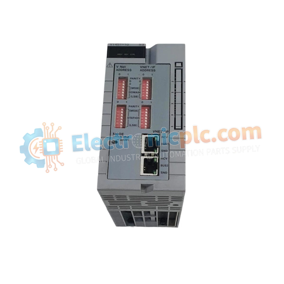
الأصالة والضمان

  • ضمان أصلي: نحن نوفر فقط قطع غيار أصلية 100%، جديدة تمامًا، ومغلقة من المصنع .
  • تغطية كاملة: كل مكون مدعوم بضمان شامل لمدة 12 شهرًا من تاريخ الشراء.
  • إمكانية التتبع: جميع المنتجات تأتي مع وثائق المصنع الأصلية والملحقات اللازمة للامتثال الكامل للمعايير الصناعية.

الدعم الفني والتوريد

  • مساعدة الخبراء: يقدم فريقنا الفني استشارات مجانية لمساعدتك في التحقق من التوافق مع أنظمة DCS و PLC.
  • مصادر القطع النادرة: متخصصون في المكونات القديمة والتي يصعب العثور عليها من Allen-Bradley و Siemens و ABB و HIMA وغيرها.
  • للاستفسارات المتعلقة بالكميات الكبيرة: تواصلوا معنا على pambo@5gplc.com للحصول على أسعار الكميات الكبيرة أو عروض أسعار المشاريع المخصصة.
عرض تفاصيل المنتج الكاملة

The Yokogawa VI451-10, also cataloged as the VI451-10 Communication Module, operates as a dedicated hardware component for facilitating data transmission and process synchronization within distributed control network architectures. This component serves as the primary communication module utilized to execute high-speed serial or bus data exchanges across Yokogawa CENTUM system platforms.

Hardware Specifications

Parameter Specification
Model VI451-10
Brand Yokogawa
Origin Japan
Weight 0.75 kg
Dimensions 13.2 cm x 5.3 cm x 6.5 cm
Operating Temp 0 to 60 deg C
Power Consumption 5 W (nominal)
Module Function Communication Interface

DCS Process Control Features

The VI451-10 integrates into the DCS architecture to provide reliable data link connectivity between control stations and external field devices. The module utilizes channel-to-channel isolation to decouple the internal control bus from external data transmission paths, preventing common-mode noise or electrical surges from affecting the integrity of the communication channel. Additionally, the module supports firmware flash compatibility, ensuring long-term adaptability for evolving network protocols and communication standards within the Yokogawa control infrastructure.

Frequently Asked Questions

Q: Is this communication module compatible with redundant system configurations?

A: Yes, the VI451-10 supports integration into redundant control setups, provided the module is mapped correctly within the system configuration database to facilitate automatic switchover.

Q: Can the module firmware be upgraded via the control bus?

A: Yes, the module supports firmware flash compatibility, allowing for updates to be performed through the system maintenance console when the station is in an appropriate maintenance state.

Field Installation Guidelines

  1. Power down the system rack or isolate the communication bus before proceeding with the physical installation of the module to prevent backplane damage.
  2. Align the module with the cabinet guide rails and insert until the connector fully engages with the backplane bus, ensuring a secure and low-resistance connection.
  3. Tighten the front panel mounting hardware to ensure proper chassis bonding and vibration resistance.
  4. Route communication cabling through dedicated EMI-shielded wireways, maintaining a minimum distance of 150 mm from high-voltage AC or inductive load power cables.
  5. Inspect the diagnostic indicator status after power-up to confirm the module has successfully performed its internal self-test and established a handshake with the host controller.