انتقل إلى معلومات المنتج
1 ل 3

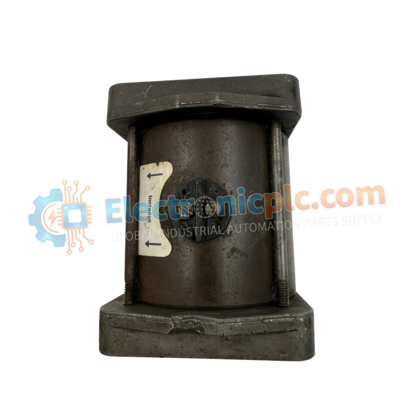
Woodward 8256-016 Electrically Powered Governor Actuator

Woodward 8256-016 Electrically Powered Governor Actuator

The Woodward 8256-016, also cataloged as the 8256-016 Actuator, operates as a dedicated hardware component for rotary fuel control and mechanical throttle positioning within Electrically Powered Governor (EPG) speed control...

18 يشاهد الناس هذا الآن

التوافرالكمية المتبقية: 6

رمز المنتج: 8256-016
بائع: Woodward

الشحن والإرجاع

توصيل موثوق به في جميع أنحاء العالم

  • شركات الشحن: يتم الشحن عبر DHL أو FedEx أو UPS أو USPS .
  • الشحن: تتم معالجة الطلبات خلال يوم عمل واحد إلى يومين، ويتم شحنها خلال 3 إلى 5 أيام عمل .
  • التتبع: يتم توفير تفاصيل التتبع الكاملة عبر البريد الإلكتروني عند الشحن.

ضمان استرداد الأموال خلال 30 يومًا

  • الضمان: فترة إرجاع لمدة 30 يومًا للمنتجات المتوفرة في المخزون والمغلفة من المصنع.
  • الشروط: يجب أن تكون المنتجات غير مفتوحة وغير مستخدمة وفي عبوتها الأصلية.
  • الأصالة: نضمن أن تكون الأجهزة أصلية 100% .

هل تحتاج إلى مزيد من التفاصيل؟ اقرأ سياسة الشحن وسياسة الاسترداد الكاملة.

الأصالة والضمان

  • ضمان أصلي: نحن نوفر فقط قطع غيار أصلية 100%، جديدة تمامًا، ومغلقة من المصنع .
  • تغطية كاملة: كل مكون مدعوم بضمان شامل لمدة 12 شهرًا من تاريخ الشراء.
  • إمكانية التتبع: جميع المنتجات تأتي مع وثائق المصنع الأصلية والملحقات اللازمة للامتثال الكامل للمعايير الصناعية.

الدعم الفني والتوريد

  • مساعدة الخبراء: يقدم فريقنا الفني استشارات مجانية لمساعدتك في التحقق من التوافق مع أنظمة DCS و PLC.
  • مصادر القطع النادرة: متخصصون في المكونات القديمة والتي يصعب العثور عليها من Allen-Bradley و Siemens و ABB و HIMA وغيرها.
  • للاستفسارات المتعلقة بالكميات الكبيرة: تواصلوا معنا على pambo@5gplc.com للحصول على أسعار الكميات الكبيرة أو عروض أسعار المشاريع المخصصة.
عرض تفاصيل المنتج الكاملة

The Woodward 8256-016, also cataloged as the 8256-016 Actuator, operates as a dedicated hardware component for rotary fuel control and mechanical throttle positioning within Electrically Powered Governor (EPG) speed control systems.

Hardware Specifications

Parameter Specification
Model 8256-016
Brand Woodward
Origin USA
Weight 3kg
Dimensions Standard Compact Profile
Operating Temp -40 to +93 deg C (-40 to +200 deg F)
Power Consumption 95 W maximum
Operating Voltage 24 VDC (20 VDC minimum to 32 VDC maximum)
Output Shaft 0.375 inch - 36 SAE serrated shaft on each end
Maximum Work Output Up to 2.3 J (1.7 ft-lb)
Steady State Speed Band +/-0.25 percent of rated speed
Idle Speed Adjustment 25 percent to 100 percent of rated speed via 50 kohm potentiometer
Magnetic Pickup Requirement Minimum 1.5 Vrms during cranking (typically 100 Hz)
Electrical Protection Requirements 10 A slow-blow fuse or circuit breaker in non-grounded battery lead
Battery Charger Requirement Minimum 5 A continuous supply when energized

Actuator Loop Feedback & Thermal Response

The drive architecture utilizes a 24 VDC electromagnetic coil assembly designed to provide precise mechanical positioning for diesel, gas, and gasoline prime movers. Actuator loop feedback response directly determines dynamic governing stability, maintaining steady-state shaft positions within +/-0.25 percent under load variations. High ambient operational capability up to +93 deg C relies on natural conduction through mounting points, demanding uniform thermal heat sink dissipation across the engine frame or skid mounting interface to prevent heat accumulation during maximum work output conditions (2.3 J).

Frequently Asked Questions

  • Q: What sizing criteria apply to the power source supplying this actuator?
  • A: The auxiliary battery charger or power unit must supply a continuous current of at least 5 A when energized, backed by a 10 A slow-blow fuse or dedicated circuit breaker installed on the non-grounded battery lead.
  • Q: What is the signal threshold required from the magnetic pickup sensor?
  • A: The system requires a minimum signal of 1.5 Vrms generated during engine cranking, typically occurring at a minimum frequency of 100 Hz, to establish a stable speed control feedback loop.
  • Q: What input component modifies the idle speed setting?
  • A: Idle speed adjustments between 25 percent and 100 percent of the rated operational speed are set using an externally connected 50 kohm potentiometer interface.

Field Installation Guidelines

  • Verify that the physical mounting surface acts as an adequate thermal heat sink, ensuring operating temperatures remain below +93 deg C under full electrical load.
  • Install a 10 A slow-blow fuse or equivalent circuit protection device directly into the positive (non-grounded) DC supply line prior to energizing the actuator.
  • Ensure output shaft linkage connects without mechanical binding or excessive radial slop to preserve transient governor response characteristics.
  • Ground all control wiring shielding at a single point to prevent ground loops from degrading magnetic pickup signal accuracy.