انتقل إلى معلومات المنتج
1 ل 3

WOODWARD 8408-921 STExcite 2010

WOODWARD 8408-921 STExcite 2010

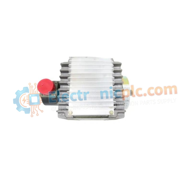
The WOODWARD 8408-921, also cataloged as the 8408-921 Ignition Module, operates as a dedicated hardware component for high-energy spark generation and arc ignition execution within gas turbine combustion networks.

Hardware...

18 يشاهد الناس هذا الآن

التوافرالكمية المتبقية: 6

رمز المنتج: 8408-921
بائع: Woodward
فئة: STExcite 2010

الشحن والإرجاع

توصيل موثوق به في جميع أنحاء العالم

  • شركات الشحن: يتم الشحن عبر DHL أو FedEx أو UPS أو USPS .
  • الشحن: تتم معالجة الطلبات خلال يوم عمل واحد إلى يومين، ويتم شحنها خلال 3 إلى 5 أيام عمل .
  • التتبع: يتم توفير تفاصيل التتبع الكاملة عبر البريد الإلكتروني عند الشحن.

ضمان استرداد الأموال خلال 30 يومًا

  • الضمان: فترة إرجاع لمدة 30 يومًا للمنتجات المتوفرة في المخزون والمغلفة من المصنع.
  • الشروط: يجب أن تكون المنتجات غير مفتوحة وغير مستخدمة وفي عبوتها الأصلية.
  • الأصالة: نضمن أن تكون الأجهزة أصلية 100% .

هل تحتاج إلى مزيد من التفاصيل؟ اقرأ سياسة الشحن وسياسة الاسترداد الكاملة.

الأصالة والضمان

  • ضمان أصلي: نحن نوفر فقط قطع غيار أصلية 100%، جديدة تمامًا، ومغلقة من المصنع .
  • تغطية كاملة: كل مكون مدعوم بضمان شامل لمدة 12 شهرًا من تاريخ الشراء.
  • إمكانية التتبع: جميع المنتجات تأتي مع وثائق المصنع الأصلية والملحقات اللازمة للامتثال الكامل للمعايير الصناعية.

الدعم الفني والتوريد

  • مساعدة الخبراء: يقدم فريقنا الفني استشارات مجانية لمساعدتك في التحقق من التوافق مع أنظمة DCS و PLC.
  • مصادر القطع النادرة: متخصصون في المكونات القديمة والتي يصعب العثور عليها من Allen-Bradley و Siemens و ABB و HIMA وغيرها.
  • للاستفسارات المتعلقة بالكميات الكبيرة: تواصلوا معنا على pambo@5gplc.com للحصول على أسعار الكميات الكبيرة أو عروض أسعار المشاريع المخصصة.
عرض تفاصيل المنتج الكاملة

The WOODWARD 8408-921, also cataloged as the 8408-921 Ignition Module, operates as a dedicated hardware component for high-energy spark generation and arc ignition execution within gas turbine combustion networks.

Hardware Specifications

Parameter Specification
Model 8408-921
Brand WOODWARD
Origin USA
Weight 5.44 kg (12.00 lbs)
Dimensions Standard
Operating Temp -20 to 55 deg C
Power Consumption 75 VA max
Input Voltage 103 to 127 VAC (115 VAC nominal, 50/60 Hz)
Output Spark Rate 1.8 +/- 0.1 sparks/second
Open Circuit Voltage 15 to 20 kV
Peak Current Output 1200 A minimum

Actuator Loop Feedback Response and High-Energy Ignition Execution

The internal digital signal processor (DSP) continuously samples line input voltage and internal thermal operating limits. Upon power application, internal power conversion stages convert 115 VAC to high-voltage discharge energy, delivering 15 to 20 kV pulses at a rate of 1.8 sparks per second to connected igniter leads. Dynamic pulse timing maintains high actuator loop feedback response and firing stability across severe combustion backpressure variations.

Frequently Asked Questions

Q: How does the internal DSP handle diagnostic fault monitoring during an ignition cycle?

A: The onboard DSP monitors input power thresholds, cycle duration, and internal temperature. If an out-of-range condition or missing igniter lead is detected, the unit de-energizes its internal fault relay and halts firing to protect the internal circuitry.

Q: What are the primary grounding requirements for the high-voltage exciter box?

A: The unit must be bonded to the main protective earth grid using a low-impedance conductor, with flexible high-voltage ignition lead shielding grounded at the exciter housing only to avoid ground loop current interference.

Field Installation Guidelines

  1. Mount the heavy-duty enclosure vertically on a flat surface using designated mounting holes to support the 5.44 kg mass.
  2. Verify that the AC supply voltage stays within the specified 103 to 127 VAC window before energizing the input power relay.
  3. Connect flexible high-voltage ignition cables to the dual-port outputs and verify secure mechanical coupling to the igniter plugs.
  4. Route low-voltage AC input lines and diagnostic fault relay cabling in separate grounded conduits away from the high-voltage discharge leads.
  5. Provide a minimum surrounding air clearance of 50 mm around the housing to facilitate thermal heat dissipation during continuous sparking sequences.