
سلة التسوق الخاصة بي
0 عنصرًا
قطع غيار أصلية للأتمتة | توصيل سريع عالمي | ضمان لمدة 12 شهرًا — [احصل على عرض سعر]

صُممت وحدة WOODWARD 9905-971 Rev(L) (وحدة الإدخال المنفصل 9905-971 Rev(L)) لمراقبة حالة الاتصال المتحملة للأعطال وتسجيل الأحداث في الوقت الفعلي عبر بنى أنظمة التحكم في التوربينات، وتوفر تنفيذًا ماديًا/كهربائيًا مباشرًا.
...التوافر: الكمية المتبقية: 6
توصيل موثوق به في جميع أنحاء العالم
ضمان استرداد الأموال خلال 30 يومًا
هل تحتاج إلى مزيد من التفاصيل؟ اقرأ سياسة الشحن وسياسة الاسترداد الكاملة.


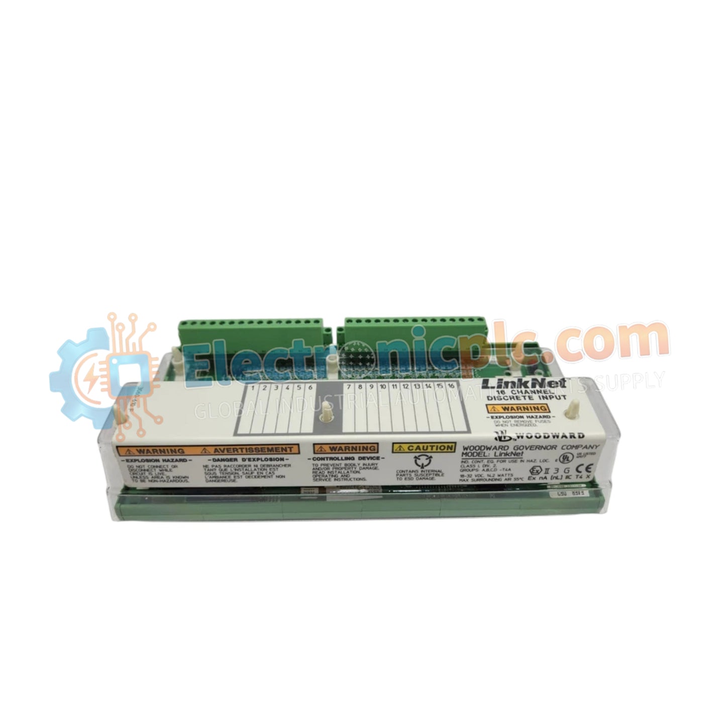
صُممت وحدة WOODWARD 9905-971 Rev(L) (وحدة الإدخال المنفصل 9905-971 Rev(L)) لمراقبة حالة الاتصال المتحملة للأعطال وتسجيل الأحداث في الوقت الفعلي عبر بنى أنظمة التحكم في التوربينات، وتوفر تنفيذًا ماديًا/كهربائيًا مباشرًا.
| المعلمة | المواصفات |
|---|---|
| النموذج | 9905-971 Rev(L) |
| العلامة التجارية | WOODWARD |
| الأصل | الولايات المتحدة الأمريكية |
| الوزن | 1.45 كجم |
| الأبعاد | حاوية وحدة LinkNet القياسية |
| درجة حرارة التشغيل | -40 إلى 85 درجة مئوية (-40 إلى +185 درجة فهرنهايت) |
| استهلاك الطاقة | 24 فولت تيار مستمر، طاقة ترطيب اسمية |
| قنوات الإدخال | 24 مدخلاً منفصلاً (معزول) |
| وقت تحديث المسح | 5 مللي ثانية |
| الختم الزمني | دقة 1 مللي ثانية |
| تكوينات المرحلات | 6 مرحلات خرج زائدة عن الحاجة مع قراءة رجعية للأعطال الكامنة |
تعالج الوحدة 24 إشارة إدخال منفصلة معزولة بمعدل تحديث سريع يبلغ 5 مللي ثانية بدقة ختم زمني تبلغ 1 مللي ثانية. تقوم دائرة القراءة الراجعة المدمجة بإجراء كشف مستمر للأعطال الكامنة عبر أزواج المرحلات دون تعطيل حالات التحكم في الإخراج، مما يحسن تحمل الأعطال في النظام واستجابة تغذية الارتداد لحلقة المحرك. توزع دوائر تحويل الطاقة المتكاملة الطاقة الحرارية بالتساوي عبر ملفات تبديد المشتت الحراري الداخلية، مما يضمن استقرار التشغيل على المدى الطويل داخل خزائن التحكم عالية الكثافة.
س: كيف يختبر منطق كشف الأعطال الكامنة مخارج المرحلات دون مقاطعة التحكم في النظام؟
ج: تقوم دائرة القراءة الراجعة المتكاملة بتدوير أزواج تلامس المرحلات وتتحقق من انتقالات الحالة المادية. إذا تم اكتشاف حالة غير صحيحة أو لحام تلامس، تقوم الدائرة التشخيصية بالإبلاغ عن خطأ وتوقف المزيد من الاختبار دون تغيير حالة التحكم النشطة في الإخراج.
س: ما هو إجراء التأريض المطلوب لمدخلات ترطيب التلامس المعزولة بالكامل بجهد 24 فولت تيار مستمر؟
ج: نظرًا لأن كل دائرة إدخال منفصلة معزولة جلفانيًا، يجب إنشاء جهد مرجعي مشترك للتيار المستمر بين مصدر ترطيب بجهد 24 فولت تيار مستمر وأطراف التوصيل المشتركة لمجموعة الإدخال لمنع أخطاء الجهد العائم.


