انتقل إلى معلومات المنتج
1 ل 3

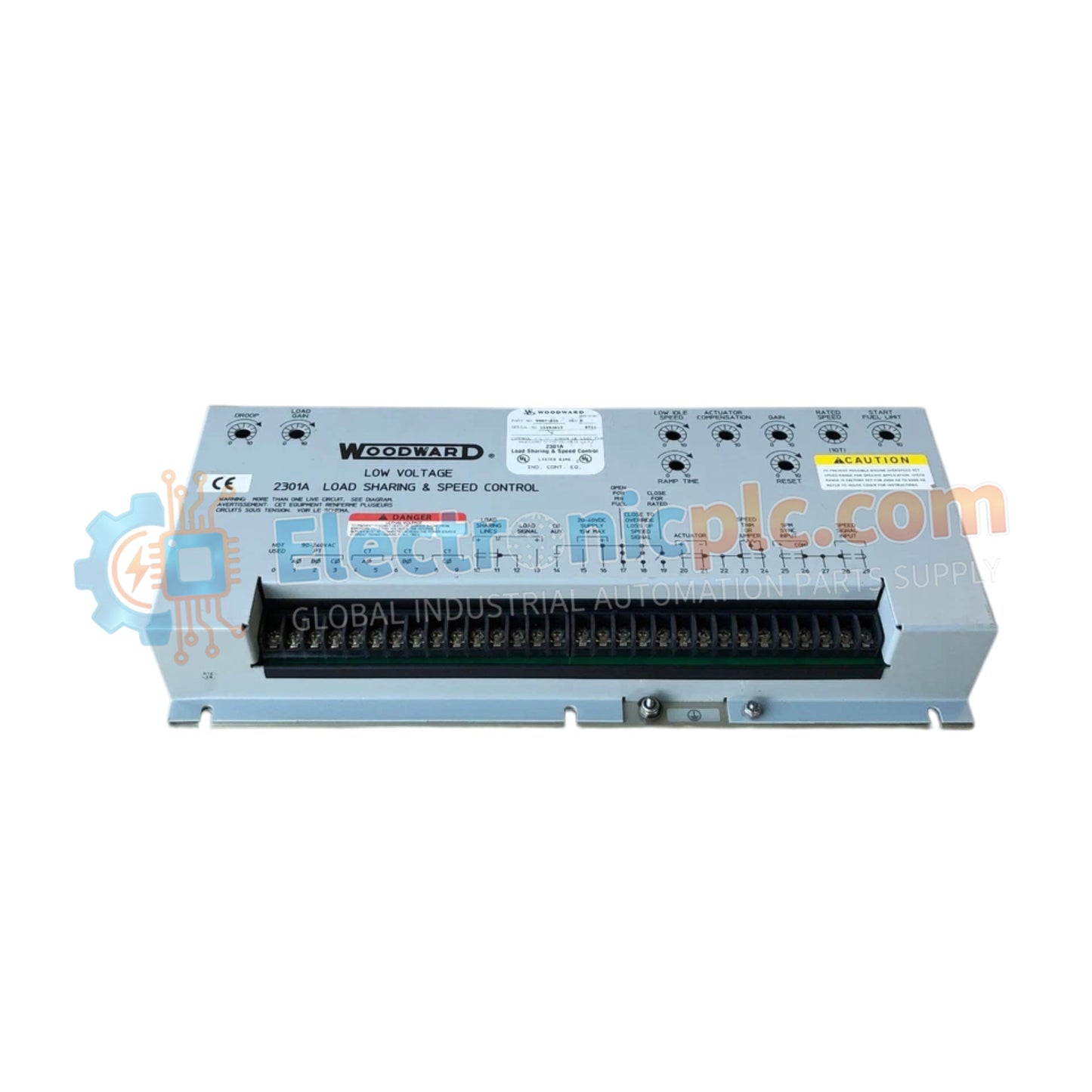
Woodward 9907-018 2301A Load Sharing and Speed Control

Woodward 9907-018 2301A Load Sharing and Speed Control

The Woodward 9907-018, also cataloged as the 9907-018 Speed Control Module, operates as a dedicated hardware component for prime mover speed regulation and proportional load distribution within 2301A Load Sharing...

23 يشاهد الناس هذا الآن

التوافرالكمية المتبقية: 6

رمز المنتج: 9907-018 2301A
بائع: Woodward

الشحن والإرجاع

توصيل موثوق به في جميع أنحاء العالم

  • شركات الشحن: يتم الشحن عبر DHL أو FedEx أو UPS أو USPS .
  • الشحن: تتم معالجة الطلبات خلال يوم عمل واحد إلى يومين، ويتم شحنها خلال 3 إلى 5 أيام عمل .
  • التتبع: يتم توفير تفاصيل التتبع الكاملة عبر البريد الإلكتروني عند الشحن.

ضمان استرداد الأموال خلال 30 يومًا

  • الضمان: فترة إرجاع لمدة 30 يومًا للمنتجات المتوفرة في المخزون والمغلفة من المصنع.
  • الشروط: يجب أن تكون المنتجات غير مفتوحة وغير مستخدمة وفي عبوتها الأصلية.
  • الأصالة: نضمن أن تكون الأجهزة أصلية 100% .

هل تحتاج إلى مزيد من التفاصيل؟ اقرأ سياسة الشحن وسياسة الاسترداد الكاملة.

الأصالة والضمان

  • ضمان أصلي: نحن نوفر فقط قطع غيار أصلية 100%، جديدة تمامًا، ومغلقة من المصنع .
  • تغطية كاملة: كل مكون مدعوم بضمان شامل لمدة 12 شهرًا من تاريخ الشراء.
  • إمكانية التتبع: جميع المنتجات تأتي مع وثائق المصنع الأصلية والملحقات اللازمة للامتثال الكامل للمعايير الصناعية.

الدعم الفني والتوريد

  • مساعدة الخبراء: يقدم فريقنا الفني استشارات مجانية لمساعدتك في التحقق من التوافق مع أنظمة DCS و PLC.
  • مصادر القطع النادرة: متخصصون في المكونات القديمة والتي يصعب العثور عليها من Allen-Bradley و Siemens و ABB و HIMA وغيرها.
  • للاستفسارات المتعلقة بالكميات الكبيرة: تواصلوا معنا على pambo@5gplc.com للحصول على أسعار الكميات الكبيرة أو عروض أسعار المشاريع المخصصة.
عرض تفاصيل المنتج الكاملة

The Woodward 9907-018, also cataloged as the 9907-018 Speed Control Module, operates as a dedicated hardware component for prime mover speed regulation and proportional load distribution within 2301A Load Sharing and Speed Control systems.

Hardware Specifications

Parameter Specification
Model 9907-018
Brand Woodward
Origin USA
Weight 1.758 kg
Dimensions 15.25 in W x 7.125 in H x 2.5 in D
Operating Temp Standard Industrial Range (-40 to +85 deg C storage)
Power Consumption 15 W or less
Series 2301A Series
Operating Voltage 20 to 40 VDC
Output Current Signal 0 to 200 mA
Certifications CE-marked (EU Low Voltage and EMC Directives), CSA certified for ordinary locations

Actuator Loop Feedback & Harmonic Distortion Suppression

The 2301A module drives hydraulic or electric fuel actuators by converting speed errors and load sharing signals into a calibrated 0 to 200 mA output current. Actuator loop feedback response directly determines dynamic governing performance under rapid step-load transients. Integrated signal conditioning limits high-frequency noise interference, providing harmonic distortion suppression across the magnetic pickup input circuit to preserve steady-state frequency control.

Frequently Asked Questions

  • Q: What cable type should be used for connecting the magnetic speed sensor?
  • A: Magnetic pickup connections require two-conductor twisted-shielded cable to maintain signal integrity, with the cable shield grounded solely at the control unit chassis.
  • Q: How is power supply isolation handled for the 20 to 40 VDC input terminals?
  • A: Operating power must be routed through dedicated fused conductors, keeping DC negative isolated from earth ground unless explicitly required by local system wiring schematics.
  • Q: What is the function of the 0 to 200 mA current output interface?
  • A: The 0 to 200 mA current loop interfaces directly with Woodward fluid/fuel actuator coils to translate electronic speed correction commands into physical valve positioning.

Field Installation Guidelines

  • Mount the unit vertically inside an enclosure using all four mounting holes to maintain stable thermal dissipation across the baseplate.
  • Route signal lines, magnetic pickup wiring, and load-sharing bus cables in separate grounded metallic conduits away from heavy AC power leads.
  • Ensure shield drain wires are connected strictly to the designated chassis terminal to avoid creating unwanted ground potential loops.
  • Verify input voltage remains strictly within the 20 to 40 VDC range under both static and dynamic generator operating states.