
سلة التسوق الخاصة بي
0 عنصرًا
قطع غيار أصلية للأتمتة | توصيل سريع عالمي | ضمان لمدة 12 شهرًا — [احصل على عرض سعر]

تعمل الوحدة WOODWARD TUG-416 8441-1013، والمصنفة أيضاً باسم وحدة التحكم في درجة الحرارة 8441-1013، كمكون مادي مخصص للمراقبة الحرارية متعددة القنوات وتحديد موضع حلقة المشغل الديناميكية ضمن شبكات التحكم في...
التوافر: الكمية المتبقية: 6
توصيل موثوق به في جميع أنحاء العالم
ضمان استرداد الأموال خلال 30 يومًا
هل تحتاج إلى مزيد من التفاصيل؟ اقرأ سياسة الشحن وسياسة الاسترداد الكاملة.

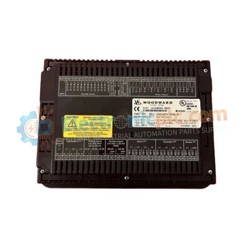
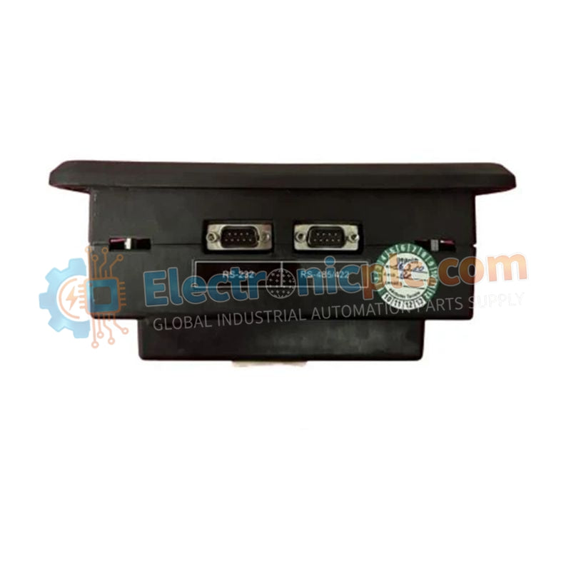
تعمل الوحدة WOODWARD TUG-416 8441-1013، والمصنفة أيضاً باسم وحدة التحكم في درجة الحرارة 8441-1013، كمكون مادي مخصص للمراقبة الحرارية متعددة القنوات وتحديد موضع حلقة المشغل الديناميكية ضمن شبكات التحكم في الآلات التوربينية.
| المعلمة | المواصفات |
|---|---|
| الموديل | TUG-416 8441-1013 |
| العلامة التجارية | WOODWARD |
| المنشأ | الولايات المتحدة الأمريكية |
| الوزن | 2 كجم |
| الأبعاد | قياسية |
| درجة حرارة التشغيل | -40 إلى 85 درجة مئوية |
| استهلاك الطاقة | 24 فولت تيار مستمر |
| المعالج | وحدة معالجة مركزية ثنائية النواة بمعمارية الطاقة، 500 ميجاهرتز |
| الذاكرة | ذاكرة تخزين مؤقت SRAM سعة 1 ميجابايت |
| المدخلات التناظرية | 32 مدخل تناظري (مثل مستشعرات درجة الحرارة Pt100) |
| المخرجات الرقمية | 16 مخرج رقمي |
| إشارة الخرج | 4-20 مللي أمبير (وقت استجابة < 1 مللي ثانية) |
| واجهات الاتصال | إيثرنت مزدوج (Modbus TCP/IP)، RS-485 معزول، CAN 2.0B، Profibus-DP (اختياري) |
يقوم معالج Power Architecture ثنائي النواة بسرعة 500 ميجاهرتز بأخذ عينات من 32 قناة تناظرية بزمن استجابة أقل من المللي ثانية (< 1 مللي ثانية)، محولاً إشارات RTD و4-20 مللي أمبير إلى متغيرات تحكم عالية السرعة. يحسب المعالج حدوداً حرارية للحلقة المغلقة لضبط استجابة تغذية حلقة المشغل في ظل الظروف الانتقالية القاسية. توجّه دوائر تكييف الطاقة الداخلية تبديد الحرارة عبر إطار الوحدة، مما يمنع الانجراف الحراري المحلي عبر مراحل التحويل التناظري إلى الرقمي عالية الكثافة.
س: كيف تقوم وحدة المعالجة المركزية ثنائية النواة بتنفيذ اكتشاف الأعطال وتكرار النظام؟
ج: تتميز وحدة المعالجة المركزية ثنائية النواة المدمجة بآليات مراقبة الأجهزة المدمجة ومنطق تسجيل الأخطاء الآلي، وتقوم باستمرار بالتحقق المتقاطع من الذاكرة وخطوط تنفيذ التعليمات البرمجية لتشغيل حالات الأمان عند اكتشاف أي تشوهات في النظام.
س: ما هي بروتوكولات الاتصال المدعومة عبر واجهات الشبكة المدمجة؟
ج: تتضمن الوحدة منفذي إيثرنت يعملان ببروتوكول Modbus TCP/IP، ومنفذ تسلسلي RS-485 معزول، وواجهة ناقل CAN 2.0B، واتصال Profibus-DP اختياري للدمج مع شبكات المصنع الرئيسية.


