سلة التسوق الخاصة بي
0 عنصرًا
قطع غيار أصلية للأتمتة | توصيل سريع عالمي | ضمان لمدة 12 شهرًا — [احصل على عرض سعر]

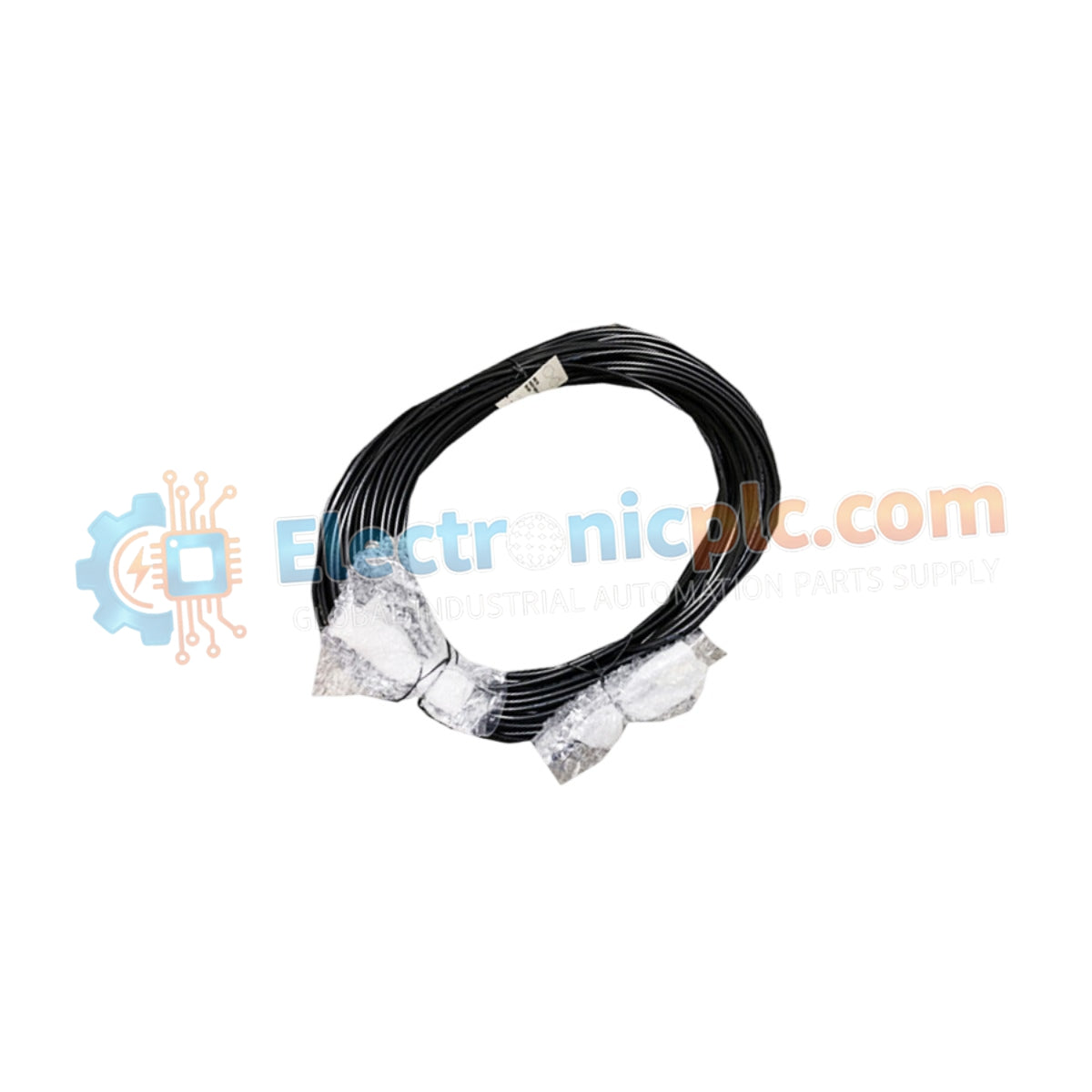
Configured for high-speed network communication within industrial control systems, the Yokogawa YCB141-M025 (YCB141-M025 Coaxial Bus Cable) provides direct physical signal transmission for V net and ER bus platforms.
التوافر: في الأوراق المالية
توصيل موثوق به في جميع أنحاء العالم
ضمان استرداد الأموال خلال 30 يومًا
هل تحتاج إلى مزيد من التفاصيل؟ اقرأ سياسة الشحن وسياسة الاسترداد الكاملة.


Configured for high-speed network communication within industrial control systems, the Yokogawa YCB141-M025 (YCB141-M025 Coaxial Bus Cable) provides direct physical signal transmission for V net and ER bus platforms.
| Model | Component Description |
|---|---|
| YCB141 | Base Coaxial Bus Cable series |
| -M025 | Cable length configuration (25 meters) |
| Parameter | Specification |
|---|---|
| Model | YCB141-M025 |
| Brand | Yokogawa |
| Origin | Japan |
| Weight | 0.85kg |
| Dimensions | 25 meters length |
| Operating Temp | -20 deg C to +70 deg C |
| Power Consumption | Passive component |
| Communication Standard | 10BASE-2 (V net / ER bus) |
| Connector Type | BNC |
| Shielding | EMI-resistant coaxial |
The YCB141-M025 is engineered to maintain low-latency data flow within Yokogawa CENTUM VP and ProSafe-RS architectures. The cable utilizes intrinsic safety (Ex i) barrier-compatible construction where required and provides DIN-rail mounting stability when used in conjunction with secondary conduit routing. The coaxial structure offers surge voltage protection limits necessary for maintaining communication link stability in high-EMI industrial zones. By adhering to 10BASE-2 standards, the cable ensures protocol conversion latencies are kept within the precise millisecond tolerances required for deterministic V net communication.
Q: Can the cable be spliced if a shorter distance is required?
A: No. Splicing or modifying the coaxial length alters the characteristic impedance of the cable, which will cause signal reflections, packet loss, and potential failure of the V net or ER bus communication link.
Q: Are there specific bending radius requirements for this coaxial cable?
A: Yes. To prevent physical damage to the internal conductor or shielding, maintain a bending radius of at least 10 times the outer diameter of the cable during installation in control cabinets or rack systems.


