انتقل إلى معلومات المنتج
1 ل 3

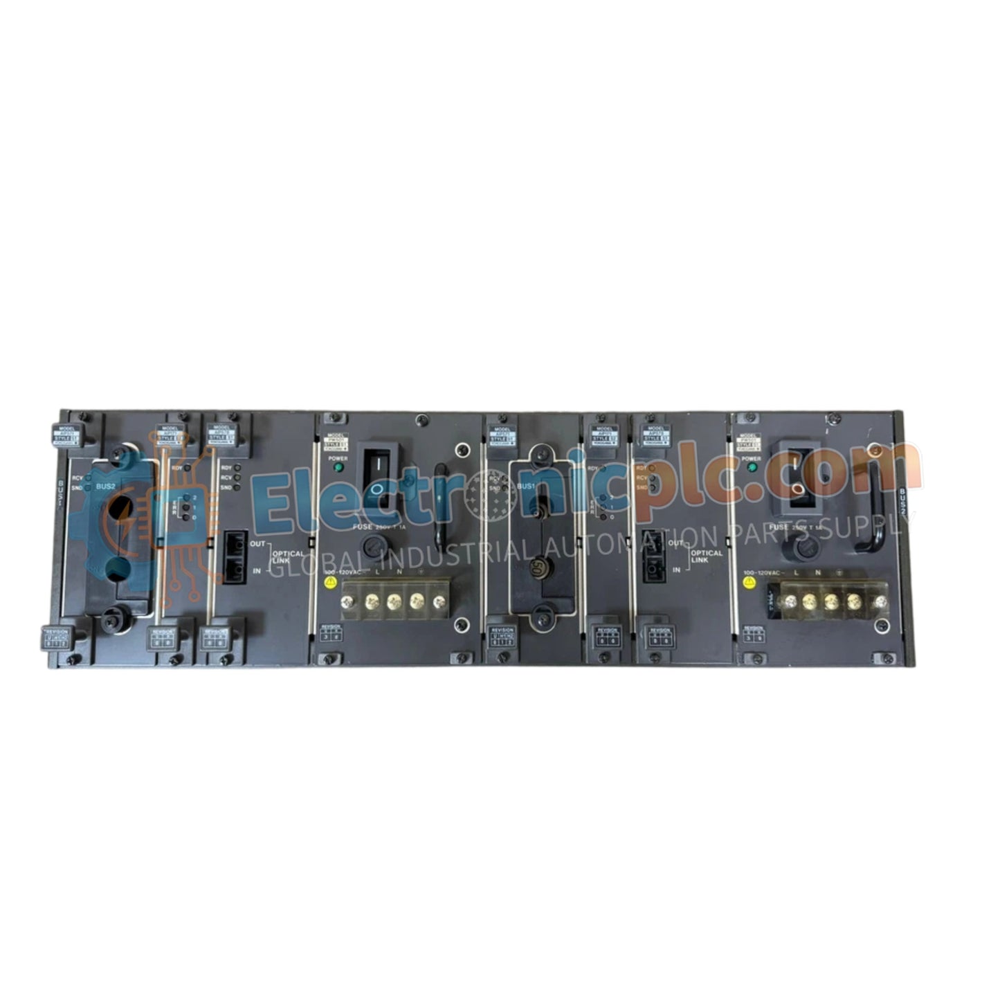
YNT511D-V42/KT Optical Bus Repeater Rack YOKOGAWA

YNT511D-V42/KT Optical Bus Repeater Rack YOKOGAWA

The YOKOGAWA YNT511D-V42/KT, also cataloged as the YNT511D Optical Bus Repeater, operates as a dedicated hardware component for signal amplification and transmission distance extension within CENTUM VP and CENTUM CS...

29 يشاهد الناس هذا الآن

التوافرفي الأوراق المالية

رمز المنتج: YNT511D-V42/KT
بائع: Yokogawa

الشحن والإرجاع

توصيل موثوق به في جميع أنحاء العالم

  • شركات الشحن: يتم الشحن عبر DHL أو FedEx أو UPS أو USPS .
  • الشحن: تتم معالجة الطلبات خلال يوم عمل واحد إلى يومين، ويتم شحنها خلال 3 إلى 5 أيام عمل .
  • التتبع: يتم توفير تفاصيل التتبع الكاملة عبر البريد الإلكتروني عند الشحن.

ضمان استرداد الأموال خلال 30 يومًا

  • الضمان: فترة إرجاع لمدة 30 يومًا للمنتجات المتوفرة في المخزون والمغلفة من المصنع.
  • الشروط: يجب أن تكون المنتجات غير مفتوحة وغير مستخدمة وفي عبوتها الأصلية.
  • الأصالة: نضمن أن تكون الأجهزة أصلية 100% .

هل تحتاج إلى مزيد من التفاصيل؟ اقرأ سياسة الشحن وسياسة الاسترداد الكاملة.

الأصالة والضمان

  • ضمان أصلي: نحن نوفر فقط قطع غيار أصلية 100%، جديدة تمامًا، ومغلقة من المصنع .
  • تغطية كاملة: كل مكون مدعوم بضمان شامل لمدة 12 شهرًا من تاريخ الشراء.
  • إمكانية التتبع: جميع المنتجات تأتي مع وثائق المصنع الأصلية والملحقات اللازمة للامتثال الكامل للمعايير الصناعية.

الدعم الفني والتوريد

  • مساعدة الخبراء: يقدم فريقنا الفني استشارات مجانية لمساعدتك في التحقق من التوافق مع أنظمة DCS و PLC.
  • مصادر القطع النادرة: متخصصون في المكونات القديمة والتي يصعب العثور عليها من Allen-Bradley و Siemens و ABB و HIMA وغيرها.
  • للاستفسارات المتعلقة بالكميات الكبيرة: تواصلوا معنا على pambo@5gplc.com للحصول على أسعار الكميات الكبيرة أو عروض أسعار المشاريع المخصصة.
عرض تفاصيل المنتج الكاملة

The YOKOGAWA YNT511D-V42/KT, also cataloged as the YNT511D Optical Bus Repeater, operates as a dedicated hardware component for signal amplification and transmission distance extension within CENTUM VP and CENTUM CS optical ESB bus networks.

Hardware Specifications

Parameter Specification
Model YNT511D-V42/KT
Brand YOKOGAWA
Origin Japan
Weight 3.6 kg
Dimensions 48.3 cm x 17.8 cm x 30.5 cm
Operating Temp 0 deg C to 50 deg C
Power Consumption 60 mA (Max)
Rack Format 19-inch standard
Module Slots 13
Isolation Voltage 1 kV DC

Channel-to-Channel Isolation and Network Connectivity

The YNT511D-V42/KT is engineered to maintain network determinism by providing optical isolation between disparate segments of the ESB bus architecture. By facilitating signal regeneration, the rack prevents data degradation over extended cabling, ensuring consistent throughput across distributed control system nodes. The 1 kV DC isolation voltage serves to decouple the optical repeater circuitry from potential ground loops or electromagnetic surges present in the wider industrial instrumentation infrastructure, supporting the integrity of the CENTUM DCS communication protocol.

Frequently Asked Questions

Q: Can the 13 slots be populated with different types of repeater modules?

A: Yes, the rack supports mixed-module configurations provided they are compatible with the backplane bus signaling and the CENTUM system requirements. Ensure all installed modules are properly seated to maintain power distribution across the backplane.

Q: What are the primary requirements for the rack's chassis grounding?

A: The rack must be connected to a low-impedance facility earth ground via the rear-mounted grounding lug. This is necessary to satisfy the 1 kV DC isolation specification and provide an effective path for transient electrical noise.

Field Installation Guidelines

  1. Mount the YNT511D-V42/KT into a standard 19-inch instrumentation rack, ensuring proper airflow around the chassis to maintain operating temperature within limits.
  2. Connect the 24 V DC power supply to the input terminals, verifying polarity before energizing the rack.
  3. Install the required optical repeater modules into the available slots, ensuring the gold-plated edge connectors are fully seated into the backplane.
  4. Route optical fibers carefully, adhering to the minimum bend radius specifications to prevent light attenuation or permanent fiber damage.
  5. Verify link activity on the installed modules upon system power-up to confirm the optical bus path has been successfully established and regenerated.