سلة التسوق الخاصة بي
0 عنصرًا
قطع غيار أصلية للأتمتة | توصيل سريع عالمي | ضمان لمدة 12 شهرًا — [احصل على عرض سعر]

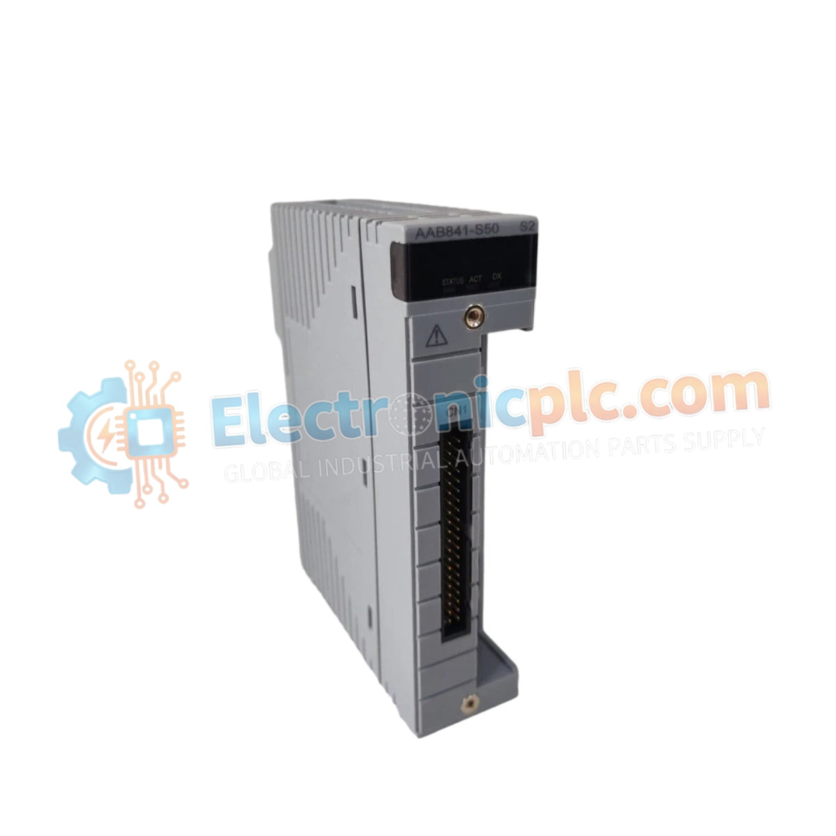
Configured for high-precision signal interfacing in process control platforms, the Yokogawa AAB841-S50 (AAB841 Analog Input/Output Module) provides direct physical/electrical execution of 8-channel voltage input and 8-channel current output signal conversion.
...التوافر: في الأوراق المالية
توصيل موثوق به في جميع أنحاء العالم
ضمان استرداد الأموال خلال 30 يومًا
هل تحتاج إلى مزيد من التفاصيل؟ اقرأ سياسة الشحن وسياسة الاسترداد الكاملة.


Configured for high-precision signal interfacing in process control platforms, the Yokogawa AAB841-S50 (AAB841 Analog Input/Output Module) provides direct physical/electrical execution of 8-channel voltage input and 8-channel current output signal conversion.
| Parameter | Specification |
|---|---|
| Model | AAB841-S50 |
| Brand | Yokogawa |
| Origin | Japan |
| Weight | 0.5 kg |
| Dimensions | Standard DIN-rail mount chassis |
| Operating Temp | -20 deg C to 70 deg C |
| Power Consumption | 5 W (Typical) |
| Input Channels | 8 (1–5 V signal range) |
| Output Channels | 8 (4–20 mA signal range) |
| Accuracy | +/- 0.2% |
| Resolution | 16-bit |
| Response Time | < 50 ms |
The integration of the AAB841-S50 into DCS architectures requires strict attention to loop protocol requirements. Since this module utilizes non-isolated channels, users must ensure proper common-mode noise suppression at the field terminal block. While the module supports standard 4-20 mA output loops, it lacks intrinsic galvanic isolation between channels. Consequently, loop-powered transmitters must be checked for ground loop potential before connection to prevent signal drift or damage to the 16-bit analog-to-digital converter front end. The AAB841-S50 relies on external cold junction compensation (CJC) if applied to thermocouple-emulated inputs, and users should verify that the termination resistor values match the system load requirements to maintain the rated +/- 0.2% accuracy.
Q: Does the AAB841-S50 support hot-swap capability during system operation?
A: No, this module is not designed for hot-swapping. Ensure the power is removed from the I/O bus and the local rack segment before inserting or removing the unit to prevent backplane bus damage or data bus corruption.
Q: How should I manage the non-isolated channel configuration?
A: Because the 8 input and 8 output channels share a common ground, it is recommended to utilize external signal isolators for each loop if the field devices are located in different potential zones to avoid interference.


