انتقل إلى معلومات المنتج
1 ل 3

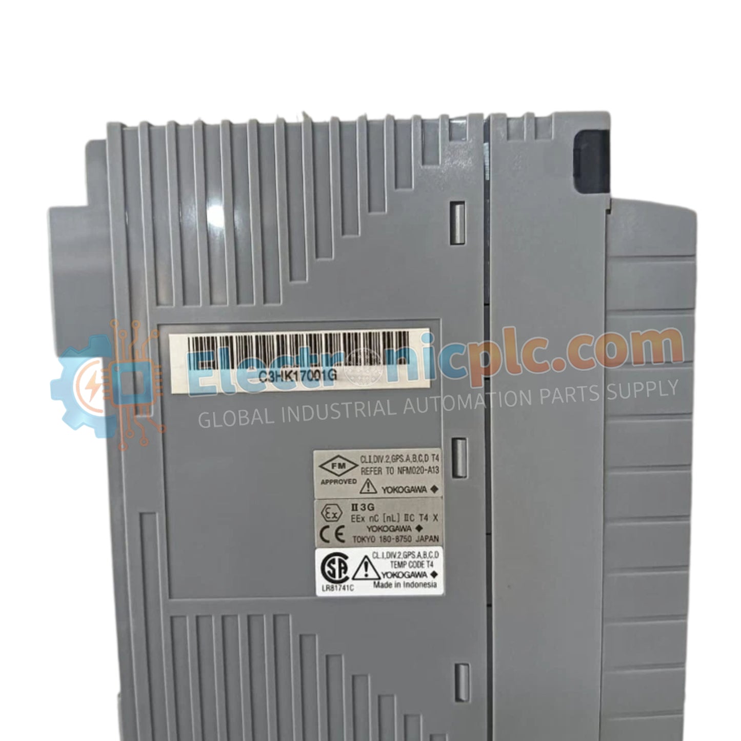
Yokogawa AAV144-S00/A4S10 Analog Input Module

Yokogawa AAV144-S00/A4S10 Analog Input Module

Configured for precision signal acquisition in process control networks, the Yokogawa AAV144-S00/A4S10 (AAV144-S00 Analog Input Module) provides direct physical/electrical execution of user-configurable analog voltage processing.

Suffix Breakdown & Model Matrix

...
21 يشاهد الناس هذا الآن

التوافرفي الأوراق المالية

رمز المنتج: AAV144-S00/A4S10
بائع: Yokogawa
Related Series:

الشحن والإرجاع

توصيل موثوق به في جميع أنحاء العالم

  • شركات الشحن: يتم الشحن عبر DHL أو FedEx أو UPS أو USPS .
  • الشحن: تتم معالجة الطلبات خلال يوم عمل واحد إلى يومين، ويتم شحنها خلال 3 إلى 5 أيام عمل .
  • التتبع: يتم توفير تفاصيل التتبع الكاملة عبر البريد الإلكتروني عند الشحن.

ضمان استرداد الأموال خلال 30 يومًا

  • الضمان: فترة إرجاع لمدة 30 يومًا للمنتجات المتوفرة في المخزون والمغلفة من المصنع.
  • الشروط: يجب أن تكون المنتجات غير مفتوحة وغير مستخدمة وفي عبوتها الأصلية.
  • الأصالة: نضمن أن تكون الأجهزة أصلية 100% .

هل تحتاج إلى مزيد من التفاصيل؟ اقرأ سياسة الشحن وسياسة الاسترداد الكاملة.

الأصالة والضمان

  • ضمان أصلي: نحن نوفر فقط قطع غيار أصلية 100%، جديدة تمامًا، ومغلقة من المصنع .
  • تغطية كاملة: كل مكون مدعوم بضمان شامل لمدة 12 شهرًا من تاريخ الشراء.
  • إمكانية التتبع: جميع المنتجات تأتي مع وثائق المصنع الأصلية والملحقات اللازمة للامتثال الكامل للمعايير الصناعية.

الدعم الفني والتوريد

  • مساعدة الخبراء: يقدم فريقنا الفني استشارات مجانية لمساعدتك في التحقق من التوافق مع أنظمة DCS و PLC.
  • مصادر القطع النادرة: متخصصون في المكونات القديمة والتي يصعب العثور عليها من Allen-Bradley و Siemens و ABB و HIMA وغيرها.
  • للاستفسارات المتعلقة بالكميات الكبيرة: تواصلوا معنا على pambo@5gplc.com للحصول على أسعار الكميات الكبيرة أو عروض أسعار المشاريع المخصصة.
عرض تفاصيل المنتج الكاملة

Configured for precision signal acquisition in process control networks, the Yokogawa AAV144-S00/A4S10 (AAV144-S00 Analog Input Module) provides direct physical/electrical execution of user-configurable analog voltage processing.

Suffix Breakdown & Model Matrix

  • AAV144-S00: Base designation for a configurable analog voltage input module.
  • A4S10: Suffix indicating specific hardware configuration for signal range and protocol support.

Hardware Specifications

Parameter Specification
Model AAV144-S00/A4S10
Brand Yokogawa
Origin JAPAN
Weight 0.5 kg
Dimensions 144 mm x 90 mm x 60 mm
Operating Temp -40 deg C to 80 deg C
Power Consumption Not Specified (24 VDC input)
Input Type Analog Voltage (user-configurable)
Output Type 4-20 mA, +/- 10 V
Accuracy +/- 0.1 % of reading

Process Control and Signal Connectivity

The AAV144-S00/A4S10 module interfaces with field instrumentation to provide scalable voltage-to-current signal conversion within DCS architectures. The module implements a standard HART protocol stack to facilitate data exchange with process sensors. Internal hardware is engineered to support channel-to-channel isolation, reducing the impact of common-mode interference on low-level analog signals. The input circuitry includes configurable voltage scaling to accommodate diverse field sensor requirements, ensuring signal integrity across the designated 0-10 V input range.

Frequently Asked Questions

Q: Can the AAV144-S00/A4S10 be reconfigured for different voltage inputs while the module is powered?

A: No. Configuration adjustments must be performed through the system software interface while the module is in an offline or maintenance state to prevent transient signal output on the current loop.

Q: Is this module capable of hot-swapping under normal operational conditions?

A: No. The AAV144-S00/A4S10 does not support hot-swapping. The module must be isolated from the 24 VDC supply and the backplane communication bus before physical removal or installation.

Field Installation Guidelines

  1. Mount the module within a standard rack enclosure, ensuring proper alignment with backplane connectors to prevent pin damage during insertion.
  2. Verify that the ambient operating environment remains within the -40 deg C to 80 deg C range, providing adequate ventilation for the specified 60 mm depth clearance.
  3. Terminate shielded signal cables at the module terminals, ensuring the shield is grounded at the cabinet entry point to minimize electromagnetic noise susceptibility.
  4. Confirm that the input scaling is correctly set in the controller configuration before energizing the field device loops.
  5. Check that all mounting screws are tightened to secure the module against vibration and to maintain a reliable earth connection to the chassis.