سلة التسوق الخاصة بي
0 عنصرًا
قطع غيار أصلية للأتمتة | توصيل سريع عالمي | ضمان لمدة 12 شهرًا — [احصل على عرض سعر]

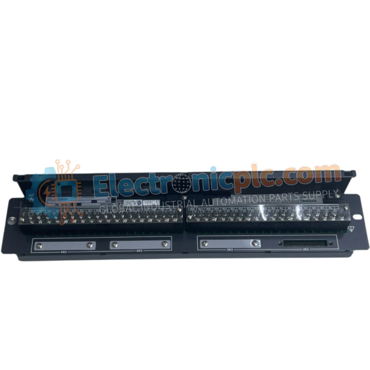
The Yokogawa AEA4D-00, also cataloged as the AEA4D-00 Terminal Board, operates as a dedicated hardware component for analog signal interface and distribution within CENTUM DCS networks.
التوافر: الكمية المتبقية: 99
توصيل موثوق به في جميع أنحاء العالم
ضمان استرداد الأموال خلال 30 يومًا
هل تحتاج إلى مزيد من التفاصيل؟ اقرأ سياسة الشحن وسياسة الاسترداد الكاملة.


The Yokogawa AEA4D-00, also cataloged as the AEA4D-00 Terminal Board, operates as a dedicated hardware component for analog signal interface and distribution within CENTUM DCS networks.
| Suffix | Description |
|---|---|
| -00 | Base terminal board configuration without integrated surge protection |
| Parameter | Specification |
|---|---|
| Model | AEA4D-00 |
| Brand | Yokogawa |
| Origin | Japan |
| Weight | 1.5 kg |
| Dimensions | Standard FIO System Footprint |
| Operating Temp | -10 deg C to +60 deg C |
| Power Consumption | Not applicable (Passive component) |
| Channels | 16 channels |
| Connection Type | M4 screws |
| Insulation Resistance | 100 MOhm at 500 VDC |
| Withstanding Voltage | 500 VAC for 1 minute |
The AEA4D-00 facilitates signal transmission between field instrumentation and the Field Instrument Input/Output (FIO) system. To ensure high-fidelity signal propagation, the board design utilizes channel-to-channel isolation architecture, minimizing crosstalk between analog loops. The interface supports 4-20 mA HART loop protocol connectivity, allowing for seamless integration of smart instrumentation into the DCS environment. Proper grounding of cable shields at the board termination points is necessary to maintain signal common-mode rejection ratios and protect the input/output circuitry from ground loops.
Q: Does the AEA4D-00 include onboard circuitry for surge voltage protection?
A: No, the AEA4D-00 is a standard terminal board; it does not contain surge protection components. If surge protection is required for field-side signals, an alternative model variant, such as the AEA4D-05, should be utilized.
Q: Is this terminal board compatible with redundant I/O module configurations?
A: Yes, the AEA4D-00 is designed to support both single and dual redundant channel configurations within the Yokogawa FIO architecture.


