سلة التسوق الخاصة بي
0 عنصرًا
قطع غيار أصلية للأتمتة | توصيل سريع عالمي | ضمان لمدة 12 شهرًا — [احصل على عرض سعر]

Configured for analog signal field termination in CENTUM VP platforms, the Yokogawa AED5D-00 (AED5D-00 Terminal Board) provides direct physical/electrical execution. This 16-channel component serves as the primary AED5D terminal board...
التوافر: في الأوراق المالية
توصيل موثوق به في جميع أنحاء العالم
ضمان استرداد الأموال خلال 30 يومًا
هل تحتاج إلى مزيد من التفاصيل؟ اقرأ سياسة الشحن وسياسة الاسترداد الكاملة.
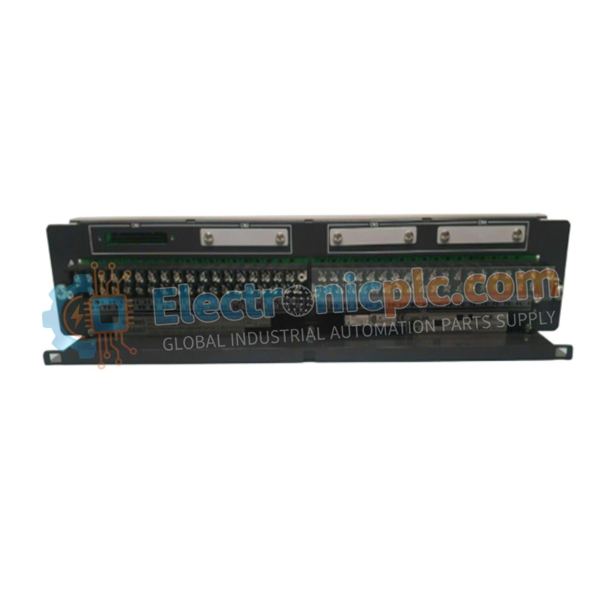
Configured for analog signal field termination in CENTUM VP platforms, the Yokogawa AED5D-00 (AED5D-00 Terminal Board) provides direct physical/electrical execution. This 16-channel component serves as the primary AED5D terminal board utilized to execute signal distribution and transient voltage suppression across process control network platforms.
| Parameter | Specification |
|---|---|
| Model | AED5D-00 |
| Brand | Yokogawa |
| Origin | Japan |
| Weight | 1.5 kg |
| Dimensions | 482.6 mm x 465.1 mm x 440 mm |
| Operating Temp | Standard industrial ambient |
| Power Consumption | Subject to loop load (Rated 4 A, 24 VDC) |
| Input Channels | 16 channels |
| Insulation Resistance | 100 MOhm at 500 VDC |
The AED5D-00 integrates a built-in surge absorber to mitigate the impact of transient voltage spikes on sensitive field instrumentation loops. The board facilitates termination via M4 screw connectors, ensuring mechanical stability for long-term field wiring. Designed for standard 19-inch rack mounting, the unit maintains signal integrity by providing a low-resistance path to the cabinet common, while meeting JEM1459 compliance for dimensional and electrical specifications. The connection to the control system is managed via the KS1 cable interface, ensuring deterministic signal path continuity.
Q: Is the AED5D-00 compatible with hazardous area (Ex i) applications?
A: No. The AED5D-00 is specified for non-explosion-proof environments. Do not install this board in areas requiring intrinsic safety barriers without external protection.
Q: How should the surge absorber be verified after a localized power surge?
A: Following a significant surge event, inspect the surge absorber component for signs of thermal damage or discoloration. Measure the insulation resistance between the signal terminals and the chassis ground to confirm the board remains within the specified 100 MOhm limit.
