سلة التسوق الخاصة بي
0 عنصرًا
قطع غيار أصلية للأتمتة | توصيل سريع عالمي | ضمان لمدة 12 شهرًا — [احصل على عرض سعر]

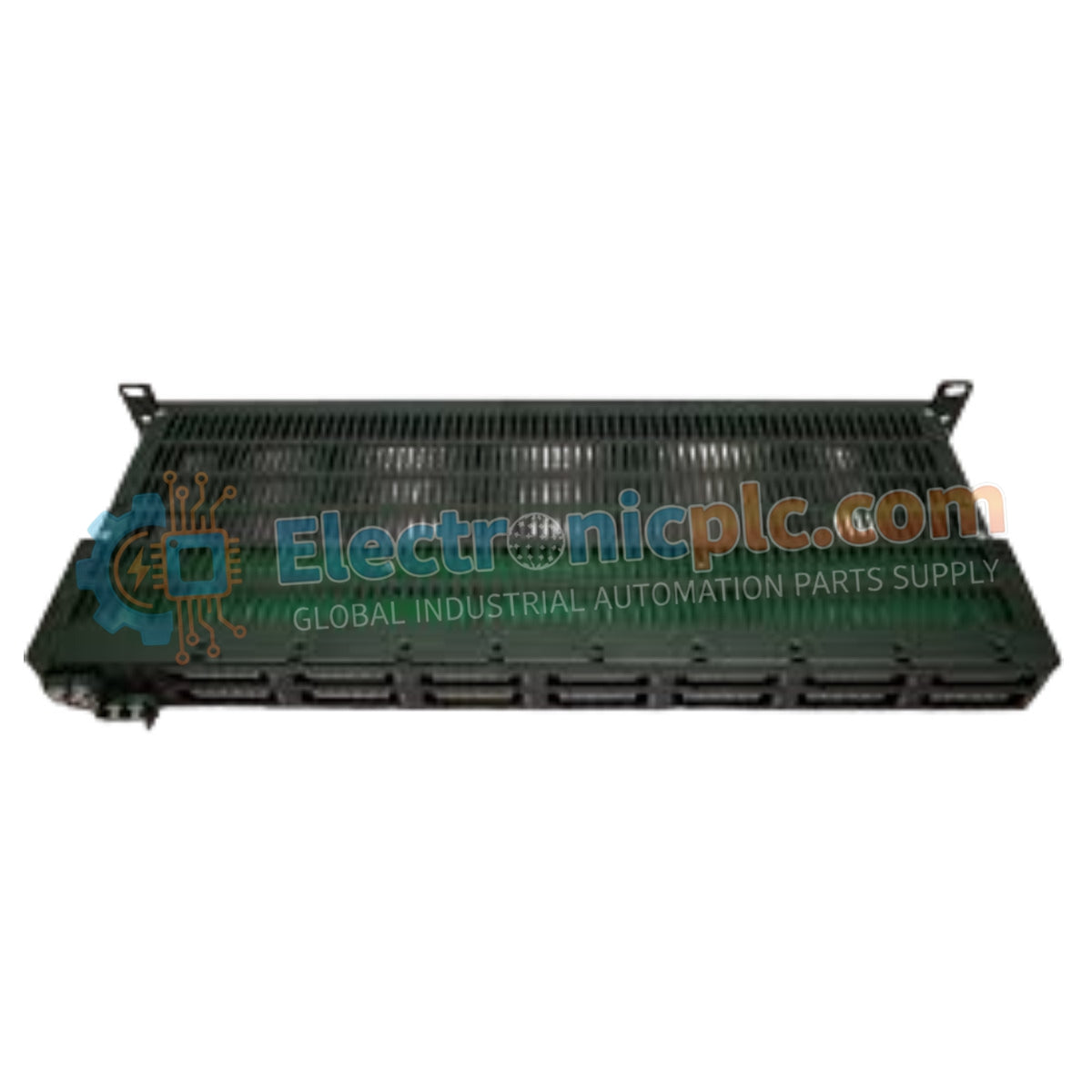
Configured for high-load power distribution in industrial control cabinets, the Yokogawa AEP7D-25 (AEP7D-25 Primary Power Supply Bus Unit) provides direct electrical execution for secondary power management and current distribution.
التوافر: في الأوراق المالية
توصيل موثوق به في جميع أنحاء العالم
ضمان استرداد الأموال خلال 30 يومًا
هل تحتاج إلى مزيد من التفاصيل؟ اقرأ سياسة الشحن وسياسة الاسترداد الكاملة.

Configured for high-load power distribution in industrial control cabinets, the Yokogawa AEP7D-25 (AEP7D-25 Primary Power Supply Bus Unit) provides direct electrical execution for secondary power management and current distribution.
The AEP7D-25 utilizes a standardized coding structure to define its electrical input and safety classification:
| Parameter | Specification |
|---|---|
| Model | AEP7D-25 |
| Brand | Yokogawa |
| Origin | Japan |
| Weight | 1.8 kg |
| Dimensions | Standard cabinet-mount form factor |
| Operating Temp | Not specified |
| Power Consumption | Max. 20 A (Total) |
| Input Voltage | 220 to 240 V AC |
| Port Current | 6 A per port |
The AEP7D-25 serves as the fundamental power distribution node for DCS and PLC racks. The unit is engineered to maintain system integrity by providing high-capacity current paths while ensuring galvanic isolation through a 1500 V AC withstanding voltage rating. Proper load balancing across the individual ports—each rated for a maximum of 6 A—is required to prevent localized thermal degradation of the bus bars. By centralizing the primary 220 to 240 V AC supply, the unit supports consistent power delivery to downstream modules, facilitating stable operation of sensitive process control instrumentation.
Q: Can this unit be used in hazardous, explosion-prone areas?
A: No. The "5" suffix indicates that this model is a basic type with no explosion protection and is intended strictly for safe, non-hazardous industrial environments.
Q: Is it permissible to connect a load exceeding 6 A to a single port?
A: No. Each port is strictly limited to a maximum current of 6 A to prevent overheating and potential circuit damage. Total current draw must not exceed the primary bus limit of 20 A.

