انتقل إلى معلومات المنتج
1 ل 3

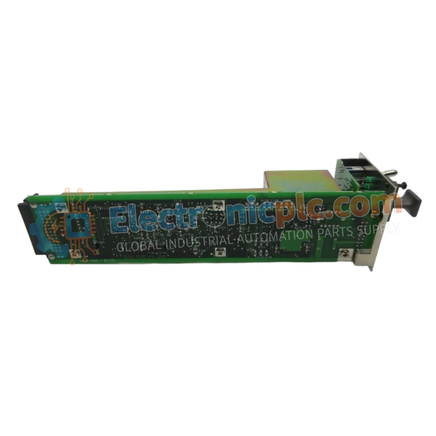
Yokogawa AIP512S2 Remote I/O Bus Connection Module

Yokogawa AIP512S2 Remote I/O Bus Connection Module

Configured for scalable integration within CENTUM industrial control networks, the Yokogawa AIP512 S2 (AIP512 Remote I/O Bus Connection Module) provides direct physical/electrical execution of ESB bus communication between control stations...

29 يشاهد الناس هذا الآن

التوافرفي الأوراق المالية

رمز المنتج: AIP512S2
بائع: Yokogawa

الشحن والإرجاع

توصيل موثوق به في جميع أنحاء العالم

  • شركات الشحن: يتم الشحن عبر DHL أو FedEx أو UPS أو USPS .
  • الشحن: تتم معالجة الطلبات خلال يوم عمل واحد إلى يومين، ويتم شحنها خلال 3 إلى 5 أيام عمل .
  • التتبع: يتم توفير تفاصيل التتبع الكاملة عبر البريد الإلكتروني عند الشحن.

ضمان استرداد الأموال خلال 30 يومًا

  • الضمان: فترة إرجاع لمدة 30 يومًا للمنتجات المتوفرة في المخزون والمغلفة من المصنع.
  • الشروط: يجب أن تكون المنتجات غير مفتوحة وغير مستخدمة وفي عبوتها الأصلية.
  • الأصالة: نضمن أن تكون الأجهزة أصلية 100% .

هل تحتاج إلى مزيد من التفاصيل؟ اقرأ سياسة الشحن وسياسة الاسترداد الكاملة.

الأصالة والضمان

  • ضمان أصلي: نحن نوفر فقط قطع غيار أصلية 100%، جديدة تمامًا، ومغلقة من المصنع .
  • تغطية كاملة: كل مكون مدعوم بضمان شامل لمدة 12 شهرًا من تاريخ الشراء.
  • إمكانية التتبع: جميع المنتجات تأتي مع وثائق المصنع الأصلية والملحقات اللازمة للامتثال الكامل للمعايير الصناعية.

الدعم الفني والتوريد

  • مساعدة الخبراء: يقدم فريقنا الفني استشارات مجانية لمساعدتك في التحقق من التوافق مع أنظمة DCS و PLC.
  • مصادر القطع النادرة: متخصصون في المكونات القديمة والتي يصعب العثور عليها من Allen-Bradley و Siemens و ABB و HIMA وغيرها.
  • للاستفسارات المتعلقة بالكميات الكبيرة: تواصلوا معنا على pambo@5gplc.com للحصول على أسعار الكميات الكبيرة أو عروض أسعار المشاريع المخصصة.
عرض تفاصيل المنتج الكاملة

Configured for scalable integration within CENTUM industrial control networks, the Yokogawa AIP512 S2 (AIP512 Remote I/O Bus Connection Module) provides direct physical/electrical execution of ESB bus communication between control stations and distributed remote I/O devices.

Suffix Breakdown & Model Matrix

  • AIP512: Base module designation for an ESB bus-compatible remote I/O interface.
  • S2: Suffix indicating the specific hardware revision for optimized signal transmission and connector compatibility.

Hardware Specifications

Parameter Specification
Model AIP512 S2
Brand Yokogawa
Origin japan
Weight 0.20 kg (0.45 lbs)
Dimensions 225 mm x 140 mm x 92 mm
Operating Temp -20 deg C to 55 deg C
Power Consumption 15 W
Current Consumption 0.5 A
Protocol ESB Bus
Transmission Speed 128 Mbps
Max Distance 10 meters

Industrial Control and Network Connectivity

The AIP512 S2 acts as the critical bridge for Remote I/O (RIO) data traffic, facilitating deterministic communication at speeds of up to 128 Mbps across the ESB bus architecture. Designed for high-speed synchronization, this module ensures that field-level signal data is transmitted to the control station with minimal latency. The interface utilizes twisted-pair cabling with secure M4 screw terminals to mitigate electromagnetic interference, providing a robust physical layer for reliable signal distribution in process automation environments.

Frequently Asked Questions

Q: Does the AIP512 S2 support hot-swapping during active system operation?

A: No. The AIP512 S2 does not support hot-swapping. Ensure that the associated control node is fully powered down and the ESB bus is inactive before initiating any maintenance or replacement of the module.

Q: Is the 10-meter maximum transmission distance strictly enforced?

A: Yes. The 128 Mbps transmission speed is optimized for the specified maximum distance of 10 meters. Exceeding this length may introduce signal attenuation or timing jitter, which can lead to data transmission errors or loss of communication with remote devices.

Field Installation Guidelines

  1. Mount the module in a well-ventilated enclosure to maintain the operating temperature between -20 deg C and 55 deg C, ensuring adequate clearance for cabling.
  2. Utilize high-quality twisted-pair cabling for the ESB bus connection, ensuring that all conductors are firmly secured to the M4 screw terminals.
  3. Observe the 10-meter limit between nodes; keep the cabling routed away from high-power equipment or frequency-drive cabling to avoid inductive noise.
  4. Ensure all shield drain wires are properly grounded at the designated chassis ground point to maintain the integrity of the high-speed data signals.
  5. Verify that the module is correctly seated and diagnostic indicators are within the normal operating range via the engineering station before enabling remote I/O communication.