انتقل إلى معلومات المنتج
1 ل 3

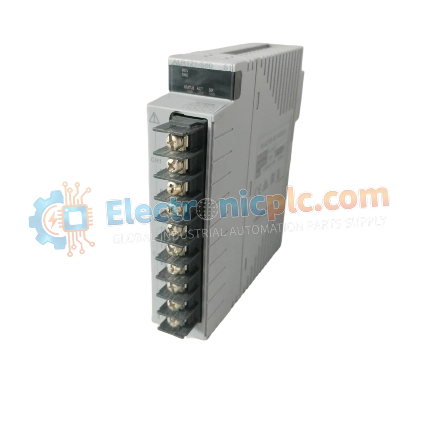
YOKOGAWA ALR121-S53 S1 Circuit Board

YOKOGAWA ALR121-S53 S1 Circuit Board

Configured for serial communication data processing in CENTUM control networks, the YOKOGAWA ALR121-S53 (ALR121 Circuit Board) provides direct physical signal conversion and protocol handling for field instrumentation.

Hardware Specifications

18 يشاهد الناس هذا الآن

التوافرفي الأوراق المالية

رمز المنتج: ALR121-S53 S1
بائع: Yokogawa
فئة: Circuit Board
Related Series:

الشحن والإرجاع

توصيل موثوق به في جميع أنحاء العالم

  • شركات الشحن: يتم الشحن عبر DHL أو FedEx أو UPS أو USPS .
  • الشحن: تتم معالجة الطلبات خلال يوم عمل واحد إلى يومين، ويتم شحنها خلال 3 إلى 5 أيام عمل .
  • التتبع: يتم توفير تفاصيل التتبع الكاملة عبر البريد الإلكتروني عند الشحن.

ضمان استرداد الأموال خلال 30 يومًا

  • الضمان: فترة إرجاع لمدة 30 يومًا للمنتجات المتوفرة في المخزون والمغلفة من المصنع.
  • الشروط: يجب أن تكون المنتجات غير مفتوحة وغير مستخدمة وفي عبوتها الأصلية.
  • الأصالة: نضمن أن تكون الأجهزة أصلية 100% .

هل تحتاج إلى مزيد من التفاصيل؟ اقرأ سياسة الشحن وسياسة الاسترداد الكاملة.

الأصالة والضمان

  • ضمان أصلي: نحن نوفر فقط قطع غيار أصلية 100%، جديدة تمامًا، ومغلقة من المصنع .
  • تغطية كاملة: كل مكون مدعوم بضمان شامل لمدة 12 شهرًا من تاريخ الشراء.
  • إمكانية التتبع: جميع المنتجات تأتي مع وثائق المصنع الأصلية والملحقات اللازمة للامتثال الكامل للمعايير الصناعية.

الدعم الفني والتوريد

  • مساعدة الخبراء: يقدم فريقنا الفني استشارات مجانية لمساعدتك في التحقق من التوافق مع أنظمة DCS و PLC.
  • مصادر القطع النادرة: متخصصون في المكونات القديمة والتي يصعب العثور عليها من Allen-Bradley و Siemens و ABB و HIMA وغيرها.
  • للاستفسارات المتعلقة بالكميات الكبيرة: تواصلوا معنا على pambo@5gplc.com للحصول على أسعار الكميات الكبيرة أو عروض أسعار المشاريع المخصصة.
عرض تفاصيل المنتج الكاملة

Configured for serial communication data processing in CENTUM control networks, the YOKOGAWA ALR121-S53 (ALR121 Circuit Board) provides direct physical signal conversion and protocol handling for field instrumentation.

Hardware Specifications

Parameter Specification
Model ALR121-S53
Brand YOKOGAWA
Origin Japan
Weight 0.3 kg
Dimensions 7.6 cm x 3 cm x 5.2 cm
Operating Temp 0 deg C to 50 deg C
Power Consumption Not specified
Function Serial Communication / Data Processing

4-20 mA HART Loop Protocol and Signal Integrity

The ALR121-S53 is engineered to manage high-speed serial data transit while maintaining the signal integrity required for process control environments. The board utilizes advanced filtering stages to support 4-20 mA HART loop protocol connectivity, ensuring that diagnostic data from smart field devices is accurately processed and transmitted to the system controller. By implementing channel-to-channel isolation on the board-level circuitry, the component effectively mitigates the risk of ground loops and common-mode noise, maintaining the high levels of precision required for critical process loops.

Frequently Asked Questions

Q: Can this circuit board be serviced or repaired at the component level?

A: No, field-level repair of circuit board components (such as soldering surface-mount devices) is not supported. The board is designed as a field-replaceable unit (FRU) and must be replaced in its entirety if diagnostic testing indicates a hardware failure.

Q: How should the board be handled to prevent electrostatic discharge (ESD) damage?

A: Always utilize an ESD-safe workstation, including a wrist strap and grounded mat, when handling the circuit board. Avoid touching the gold-plated edge connectors or high-density integrated circuits to prevent transient voltage damage to the board's internal logic.

Field Installation Guidelines

  1. Power down the corresponding I/O rack or communication interface unit before attempting to access the interior assembly.
  2. Remove the existing board by gently disengaging the retention clips or securing screws, ensuring the unit is pulled straight out to avoid damaging the backplane pins.
  3. Align the ALR121-S53 carefully with the slot guide rails; apply firm, uniform pressure to the board edges until the connector is fully seated.
  4. Secure the board using the provided mounting hardware to ensure high-frequency vibration resistance.
  5. Perform a system-level diagnostic check after installation to confirm that the controller recognizes the board and that communication status LEDs indicate a normal link state.