سلة التسوق الخاصة بي
0 عنصرًا
قطع غيار أصلية للأتمتة | توصيل سريع عالمي | ضمان لمدة 12 شهرًا — [احصل على عرض سعر]

The Yokogawa ANR10D-415, also cataloged as the ANR10D-415 Node Interface Chassis, operates as a dedicated hardware component for field signal distribution and network bus termination within CENTUM CS and CENTUM...
التوافر: الكمية المتبقية: 99
توصيل موثوق به في جميع أنحاء العالم
ضمان استرداد الأموال خلال 30 يومًا
هل تحتاج إلى مزيد من التفاصيل؟ اقرأ سياسة الشحن وسياسة الاسترداد الكاملة.
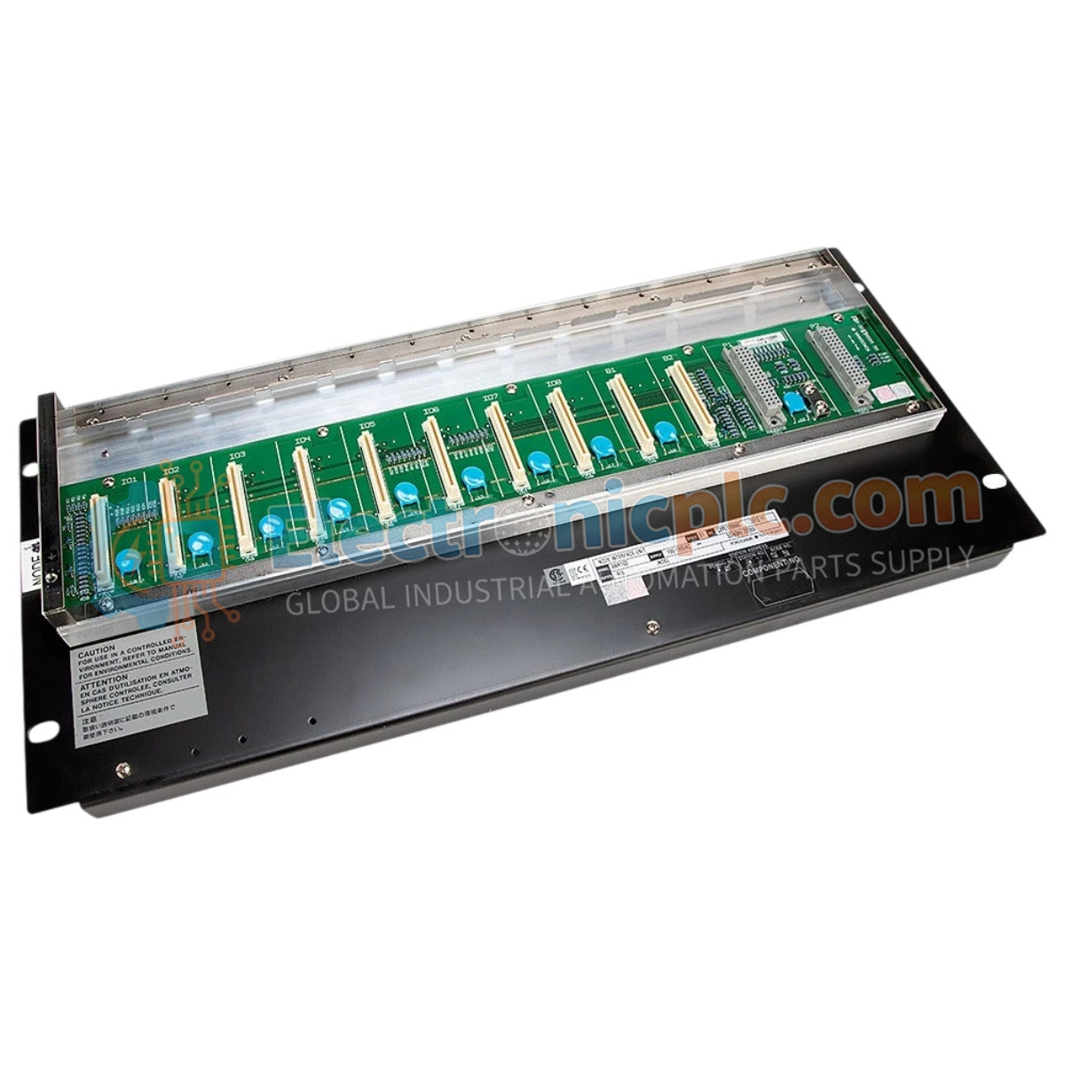
The Yokogawa ANR10D-415, also cataloged as the ANR10D-415 Node Interface Chassis, operates as a dedicated hardware component for field signal distribution and network bus termination within CENTUM CS and CENTUM VP control systems.
| Parameter | Specification |
|---|---|
| Model | ANR10D-415 |
| Brand | Yokogawa |
| Origin | Japan |
| Weight | 2.6 kg |
| Dimensions | 17.8 cm x 22.9 cm x 5.1 cm |
| Operating Temp | Standard industrial range |
| Power Consumption | Backplane dependent |
The ANR10D-415 facilitates the physical connection between the I/O nodes and the control bus, ensuring data consistency across the network. The chassis design incorporates internal signal routing to maintain galvanic isolation between the bus power and the communication channels, preventing potential ground loops. The mechanical architecture supports high-density module mounting, while maintaining the shielding requirements necessary for electromagnetic compatibility in distributed control environments.
Q: Does the ANR10D-415 chassis support hot-swapping of mounted I/O modules?
A: Yes, the chassis backplane is designed to support hot-swapping of interface modules while the system is powered. However, the system configuration must be updated to manage the module removal, and physical extraction should be performed with standard anti-static precautions to protect the backplane pins.
Q: Is external termination required for the network bus connection on this chassis?
A: Termination depends on the physical location of the ANR10D-415 within the bus topology. If the chassis acts as an end-of-line node, appropriate bus terminators must be installed to prevent signal reflections that could compromise network communication velocity.
