سلة التسوق الخاصة بي
0 عنصرًا
قطع غيار أصلية للأتمتة | توصيل سريع عالمي | ضمان لمدة 12 شهرًا — [احصل على عرض سعر]

The YOKOGAWA ANT401-50/CU1T, also cataloged as the ANT401 Optical ESB Bus Repeater Master Module, operates as a dedicated hardware component for extending the reach of the ESB bus architecture across...
التوافر: الكمية المتبقية: 99
توصيل موثوق به في جميع أنحاء العالم
ضمان استرداد الأموال خلال 30 يومًا
هل تحتاج إلى مزيد من التفاصيل؟ اقرأ سياسة الشحن وسياسة الاسترداد الكاملة.
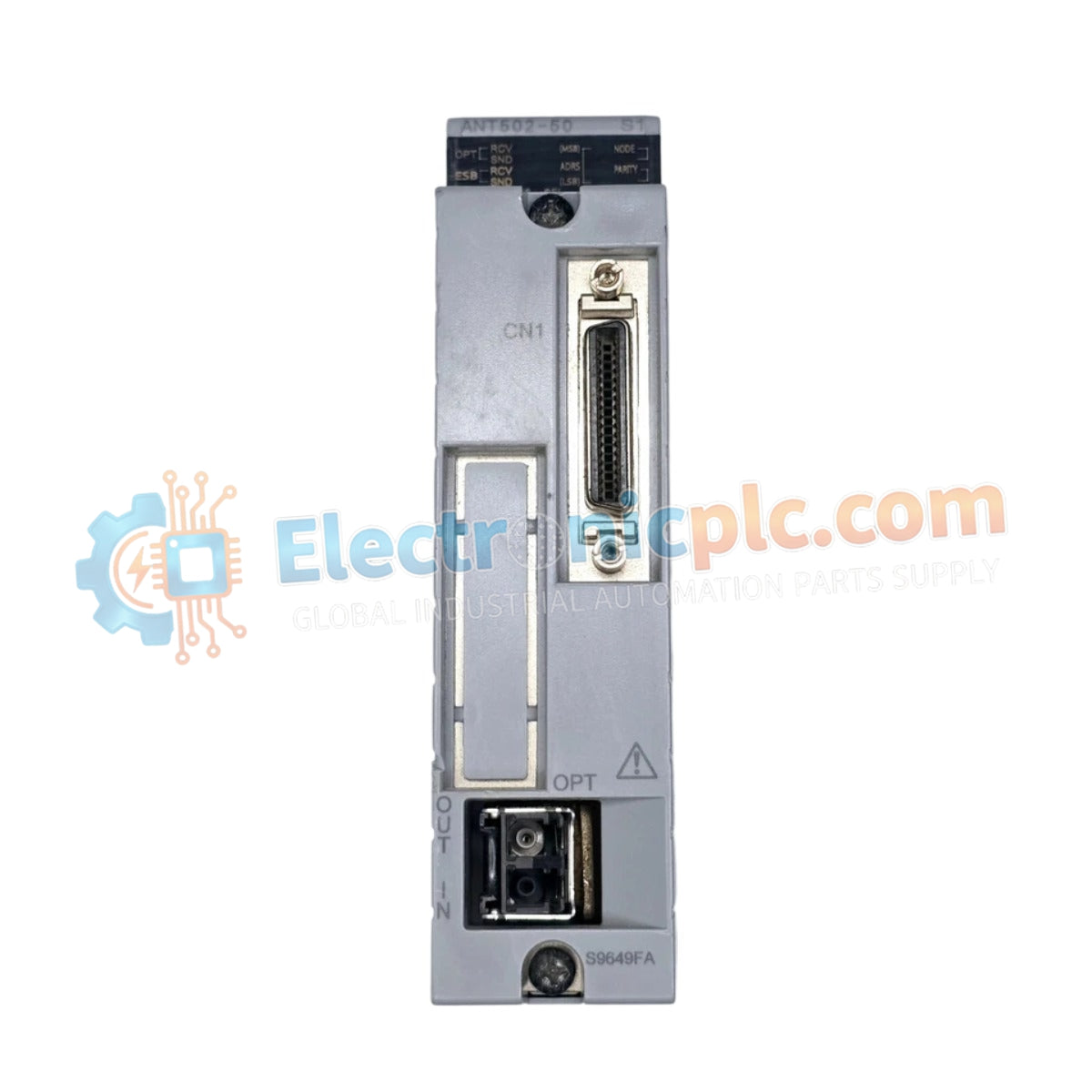

The YOKOGAWA ANT401-50/CU1T, also cataloged as the ANT401 Optical ESB Bus Repeater Master Module, operates as a dedicated hardware component for extending the reach of the ESB bus architecture across distributed control system (DCS) platforms.
| Parameter | Specification |
|---|---|
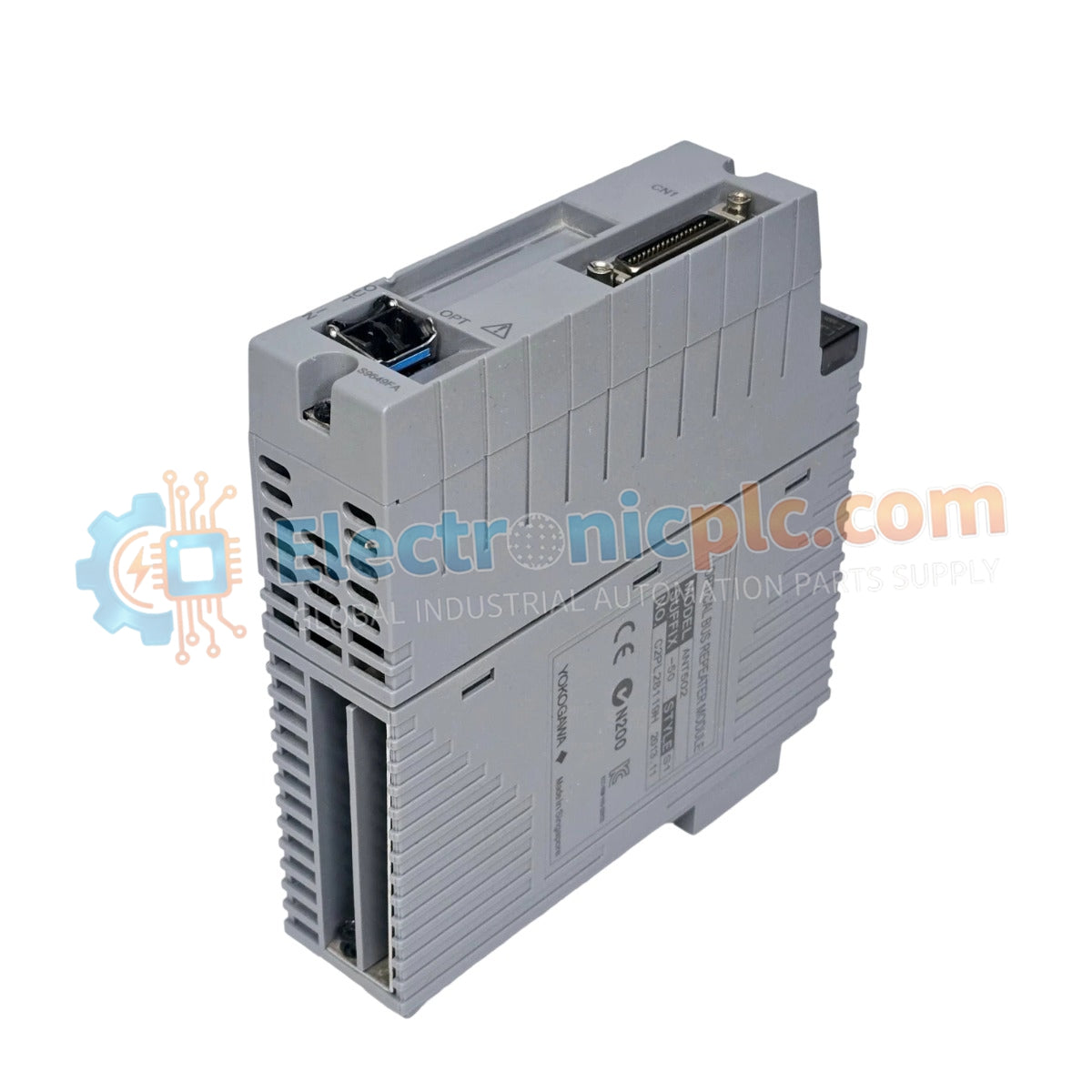
| Model | ANT401-50/CU1T |
| Brand | YOKOGAWA |
| Origin | japan |
| Weight | 0.3kg |
| Dimensions | Standard Module Format |
| Operating Temp | Standard Industrial Range |
| Power Consumption | Subject to backplane load |
| Range | 5 km optical transmission |
| Interface | ESB Bus (Optical) |
The ANT401-50/CU1T facilitates high-speed data transmission over optical fiber, enabling the extension of ESB bus segments up to 5 km. This module provides essential signal conversion from electrical ESB bus protocols to optical signals, ensuring deterministic data exchange between the control station and remote I/O nodes. The architecture employs channel-to-channel isolation to prevent ground potential differences between distant nodes from affecting the communication bus. The integrated terminator in the /CU1T connector unit minimizes signal reflections at the end of the ESB bus segment, maintaining packet integrity for real-time control synchronization.
Q: Can this master module be used with any fiber-optic cable type?
A: No, the optical interface is calibrated for specific fiber-optic standards compatible with Yokogawa control infrastructure. Using incompatible fiber-optic cabling can lead to excessive signal attenuation and communication failures.
Q: Is the ANT401-50/CU1T capable of managing redundant optical segments?
A: Yes, the module supports redundancy within the ESB bus architecture. Proper configuration of the master and slave modules is necessary to ensure seamless failover in the event of an optical path fault.


