
سلة التسوق الخاصة بي
0 عنصرًا
قطع غيار أصلية للأتمتة | توصيل سريع عالمي | ضمان لمدة 12 شهرًا — [احصل على عرض سعر]

تم تصميم YOKOGAWA ANT401-50/CU1T (ANT401-50 وحدة مكرر ناقل ESB البصري الرئيسية) لتمديد إشارة المسافات الطويلة في شبكات التحكم الموزعة، ويوفر التنفيذ المادي/الكهربائي المباشر لتحويل الإشارة البصرية. تسهل هذه الوحدة نقل بيانات ناقل ESB...
التوافر: في الأوراق المالية
توصيل موثوق به في جميع أنحاء العالم
ضمان استرداد الأموال خلال 30 يومًا
هل تحتاج إلى مزيد من التفاصيل؟ اقرأ سياسة الشحن وسياسة الاسترداد الكاملة.


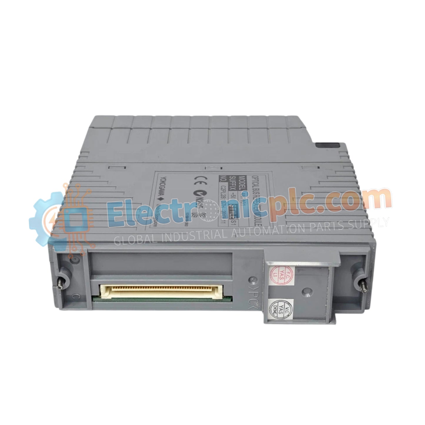
تم تصميم YOKOGAWA ANT401-50/CU1T (ANT401-50 وحدة مكرر ناقل ESB البصري الرئيسية) لتمديد إشارة المسافات الطويلة في شبكات التحكم الموزعة، ويوفر التنفيذ المادي/الكهربائي المباشر لتحويل الإشارة البصرية. تسهل هذه الوحدة نقل بيانات ناقل ESB عبر نطاقات تصل إلى 50 كم، وتعمل كواجهة رئيسية لمجموعات الأجهزة عن بعد.
يتكون ANT401-50/CU1T من متغيرات بناء محددة محسّنة لطبولوجيا الشبكة:
ANT401-50: يحدد الوحدة الأساسية الرئيسية لمكرر ناقل ESB البصري.
5: تعين الإصدار القياسي بدون شهادة حماية متكاملة من الانفجار.
0: يحدد مجموعة الوظائف الأساسية.
/CU1T: يشير إلى تضمين وحدة موصل مجهزة بموصل ناقل ESB.
| المعلمة | المواصفات |
| النموذج | ANT401-50/CU1T |
| العلامة التجارية | YOKOGAWA |
| الأصل | اليابان |
| الوزن | 0.25 كجم |
| الأبعاد | صندوق الوحدة القياسي |
| درجة حرارة التشغيل | المعيار الصناعي |
| استهلاك الطاقة | 0.5 أمبير |
| نطاق الإرسال | 5 كم إلى 50 كم |
يستخدم ANT401-50 معالجة الإشارات الداخلية لضمان استقرار اتصال ناقل ESB عبر مسارات الألياف الضوئية الممتدة. عن طريق تحويل إشارات الناقل الكهربائية إلى إشارات بصرية، تحافظ الوحدة على بروتوكولات التوقيت الصارمة المطلوبة لـ FOUNDATION Fieldbus وبنى الاتصال الحتمية المماثلة. يضمن هذا التنفيذ بقاء زمن الوصول ضمن التفاوتات المحددة للنظام، مما يمنع تصادم البيانات أو فقدان الإطارات أثناء عمليات التشغيل متعددة الأسياد عبر عقد التحكم الموزعة جغرافيًا.
س: هل يمكن استخدام ANT401-50/CU1T في تكوين مزدوج زائد عن الحاجة؟
ج: نعم، تم تصميم الوحدة لدعم التكوينات الفردية والمزدوجة الزائدة عن الحاجة. عند التنفيذ في زوج زائد عن الحاجة، تضمن الوحدة الرئيسية التبديل التلقائي إلى وصلة الاتصال الثانوية دون تعطيل حركة مرور الناقل.
س: هل وحدة الموصل /CU1T ضرورية للعقدة النهائية في سلسلة ناقل ESB؟
ج: نعم، تتضمن /CU1T موصلًا مطلوبًا لمطابقة مقاومة الخط في نهاية ناقل ESB. قد يؤدي الفشل في إنهاء جزء الناقل بشكل صحيح إلى انعكاسات الإشارة وأخطاء الاتصال.
تأكد من تنظيف موصلات كبل الألياف الضوئية (LC/SC/ST حسب الاقتضاء) بمناديل خالية من الوبر وكحول الأيزوبروبيل المعتمدة قبل إدخالها في منافذ جهاز الإرسال والاستقبال لتقليل فقد الإدخال البصري.
إذا كنت تقوم بالتثبيت في تكوين زائد عن الحاجة، فتأكد من تعيين كلتا الوحدتين لعناوين ناقل ESB الصحيحة في برنامج وحدة التحكم قبل تشغيل أجزاء الناقل.
ثبت الوحدة في الفتحة المخصصة على اللوحة الأساسية باستخدام براغي التثبيت المدمجة لضمان اتصال كهربائي قوي باللوحة الخلفية.
مرر الكابلات البصرية داخل القنوات المخصصة لحماية الألياف الزجاجية من نصف قطر الانحناء المفرط أو الضغط الميكانيكي.
تحقق من تطبيق مفتاح المنهي أو وحدة الموصل (/CU1T) بشكل صحيح في الموضع النهائي للخط الفعلي على الناقل للحفاظ على سلامة الإشارة.


