سلة التسوق الخاصة بي
0 عنصرًا
قطع غيار أصلية للأتمتة | توصيل سريع عالمي | ضمان لمدة 12 شهرًا — [احصل على عرض سعر]

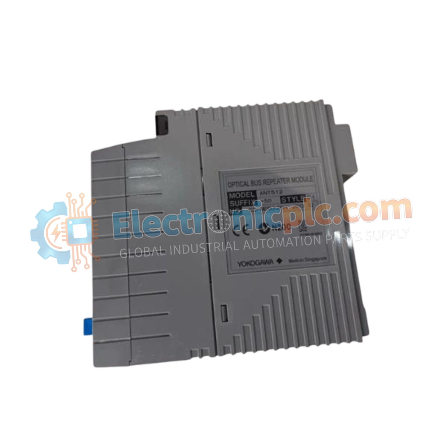
Configured for long-range network extension within CENTUM VP control architectures, the Yokogawa ANT502-50/BU1A (ANT502-50/BU1A Optical ESB Bus Repeater) provides direct physical signal conversion for extended distance I/O bus communication.
التوافر: في الأوراق المالية
توصيل موثوق به في جميع أنحاء العالم
ضمان استرداد الأموال خلال 30 يومًا
هل تحتاج إلى مزيد من التفاصيل؟ اقرأ سياسة الشحن وسياسة الاسترداد الكاملة.

Configured for long-range network extension within CENTUM VP control architectures, the Yokogawa ANT502-50/BU1A (ANT502-50/BU1A Optical ESB Bus Repeater) provides direct physical signal conversion for extended distance I/O bus communication.
| Parameter | Specification |
|---|---|
| Model | ANT502-50/BU1A |
| Brand | Yokogawa |
| Origin | Japan |
| Weight | 0.25 kg |
| Dimensions | Standard industrial module profile |
| Operating Temp | Standard industrial range |
| Current Consumption | 0.5 A |
| Transmission Distance | Up to 5 km |
| Max Connectable Stages | 2 (chain configuration) |
| Max Connections | 8 (chain and star configuration) |
The ANT502-50/BU1A architecture is engineered to maintain deterministic communication across extended distances in CENTUM VP distributed control systems. By converting electrical bus signals into optical pulses, the module effectively bypasses the distance limitations of copper-based ESB (Extended Serial Bus) connections, supporting runs of up to 5 km. This functionality allows for the physical decentralization of I/O nodes while maintaining the high-speed, low-latency performance required for real-time process monitoring. The module supports flexible topologies, including chain and star configurations, enabling high-density I/O distribution across extensive plant facilities.
Q: Does the ANT502-50/BU1A require a specific type of optical fiber for the 5 km transmission distance?
A: Yes. The module is designed to operate with standard industrial-grade optical fiber cabling suitable for long-distance communication; ensure the fiber specifications (core diameter, attenuation loss) align with the requirements for ESB bus signal transmission to guarantee data integrity.
Q: Can the repeater slave be mixed with standard copper ESB cabling in the same bus loop?
A: Yes. The optical repeater acts as a bridge. However, the total number of stages and connections must strictly adhere to the system design limits (maximum of 2 stages in chain configuration) to prevent timing violations or synchronization errors on the ESB bus.

