سلة التسوق الخاصة بي
0 عنصرًا
قطع غيار أصلية للأتمتة | توصيل سريع عالمي | ضمان لمدة 12 شهرًا — [احصل على عرض سعر]

Configured for precise signal conversion in CENTUM VP DCS platforms, the Yokogawa ASI533-S00/SS3S0 (ASI533-S00 Analog Output Module) provides direct electrical execution of control commands to field-mounted actuators and valves.
التوافر: في الأوراق المالية
توصيل موثوق به في جميع أنحاء العالم
ضمان استرداد الأموال خلال 30 يومًا
هل تحتاج إلى مزيد من التفاصيل؟ اقرأ سياسة الشحن وسياسة الاسترداد الكاملة.
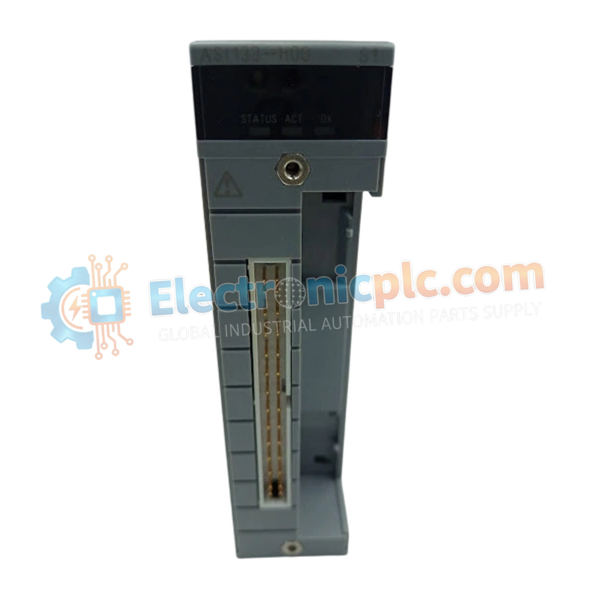
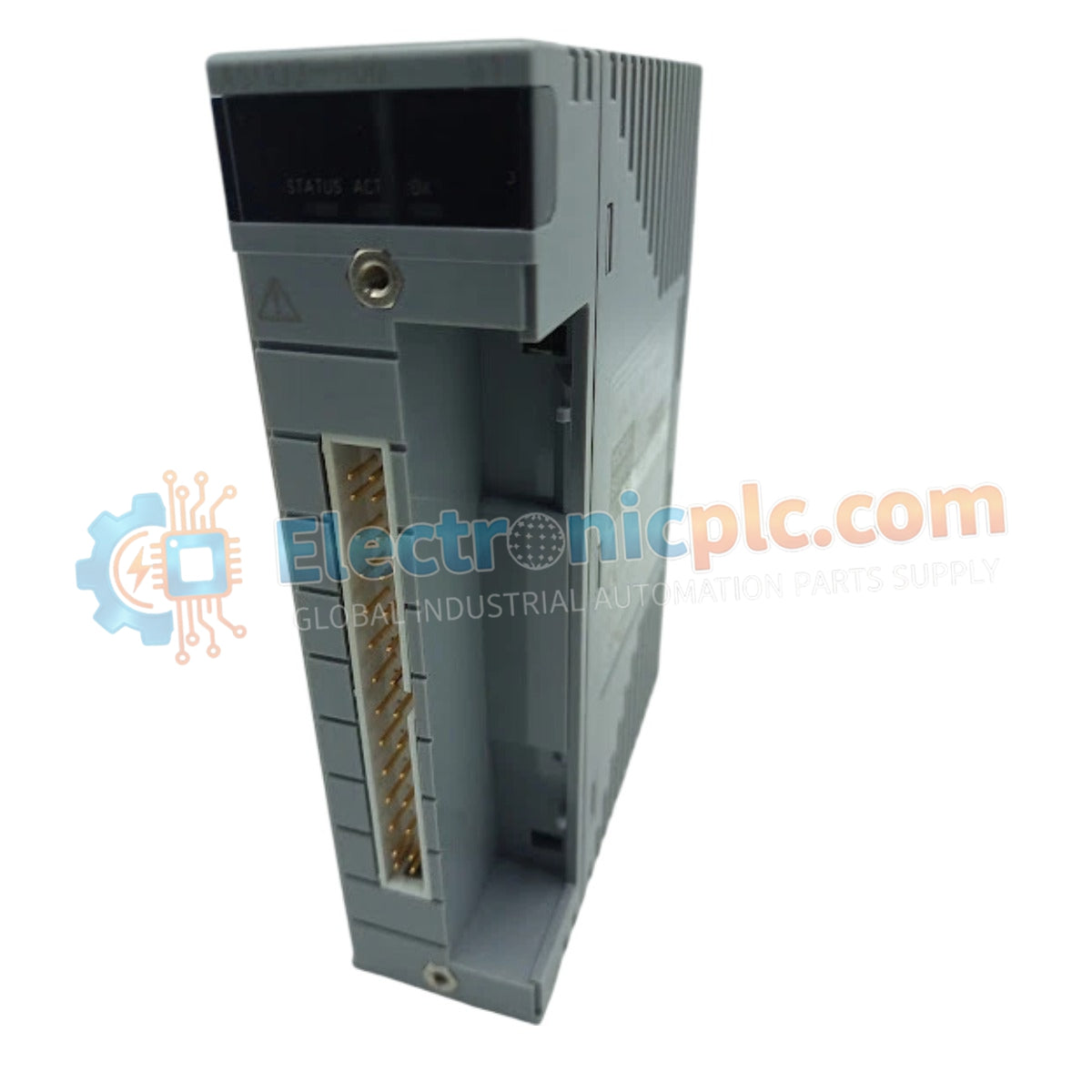
Configured for precise signal conversion in CENTUM VP DCS platforms, the Yokogawa ASI533-S00/SS3S0 (ASI533-S00 Analog Output Module) provides direct electrical execution of control commands to field-mounted actuators and valves.
| Parameter | Specification |
|---|---|
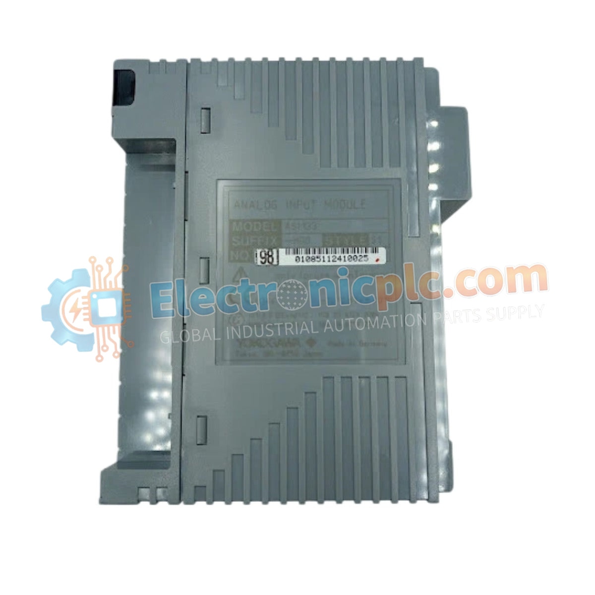
| Model | ASI533-S00 / SS3S0 |
| Brand | Yokogawa |
| Origin | Japan |
| Weight | 0.30 kg |
| Dimensions | 282 mm (W) x 210 mm (H) x 20 mm (D) |
| Operating Temp | Not specified (Standard industrial limits apply) |
| Power Consumption | 150 mA (5 V DC); 350 mA (24 V DC) |
| Output Channels | 8 Channels |
| Output Signal | 4 to 20 mA DC |
| Load Resistance | 0 to 750 Ohm at 20 mA; 0 to 600 Ohm at 23 mA |
| Response Time | 100 ms (Step response) |
| Update Period | 10 ms |
| Isolation | 1500 V AC |
The module facilitates seamless integration within Yokogawa distributed control architectures by supporting the 4-20 mA HART loop protocol. Each of the 8 channels features independent galvanic isolation, ensuring channel-to-channel isolation and minimizing common-mode interference during critical valve positioning tasks. The inclusion of HART communication allows for remote configuration and diagnostic data acquisition from smart field devices without interrupting the primary control loop.
Q: Does the ASI533-S00 support hot-swapping during active DCS operation?
A: Operation procedures for hot-swapping are subject to the specific base plate and system bus configuration of the CENTUM VP rack. Always ensure the system is in a redundant state if required by the cabinet safety protocol before module extraction.
Q: How is the load resistance affected when operating at the maximum 23 mA output?
A: The allowable load resistance reduces from 750 Ohm to 600 Ohm when the output current reaches the 23 mA threshold to maintain signal linearity and prevent output stage saturation.
Q: Is external power required for the 4-20 mA output loops?
A: The module is designed to provide active current signals. Ensure that field wiring complies with the specified loop resistance limits to prevent voltage drop issues at the actuator interface.


