سلة التسوق الخاصة بي
0 عنصرًا
قطع غيار أصلية للأتمتة | توصيل سريع عالمي | ضمان لمدة 12 شهرًا — [احصل على عرض سعر]

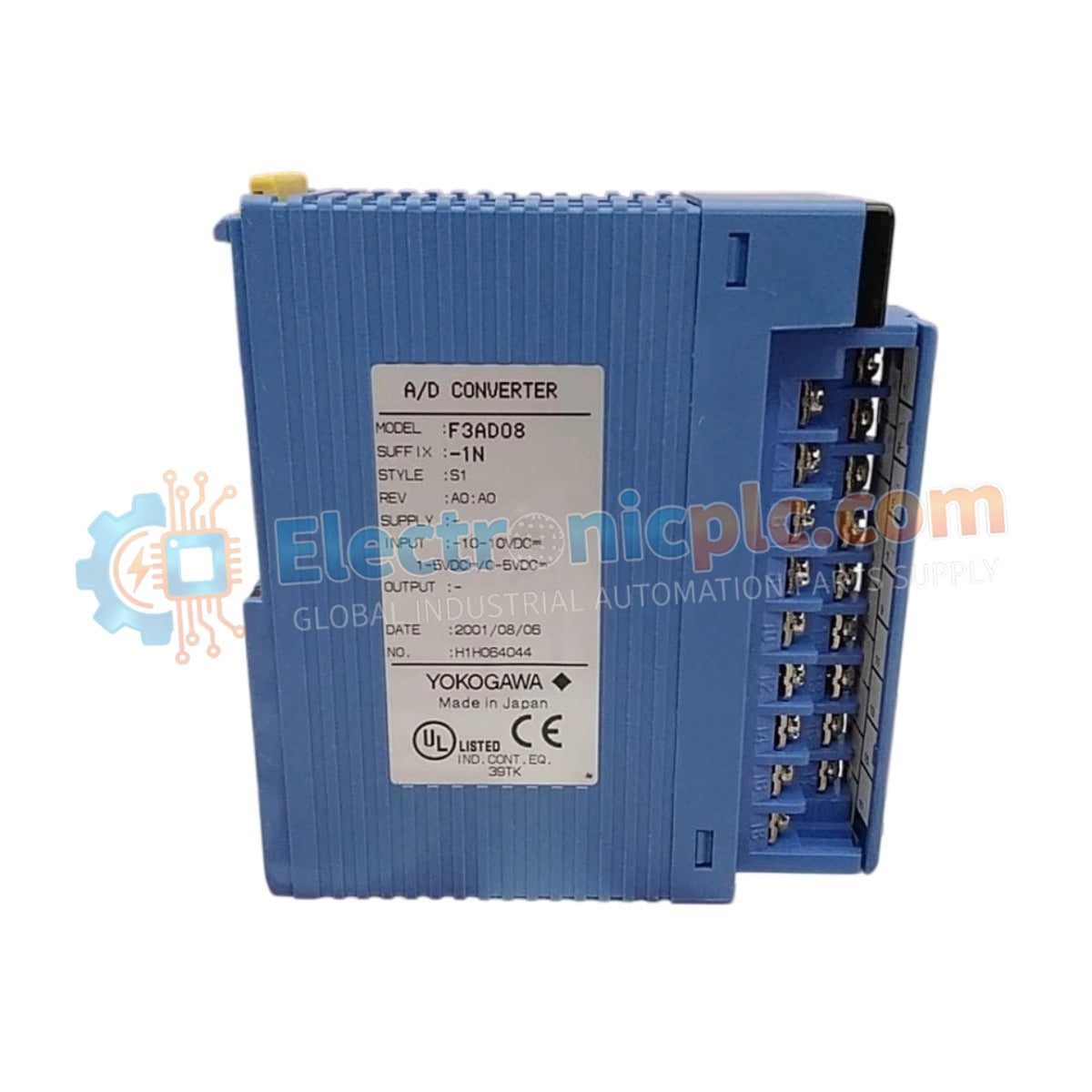
Configured for high-speed signal acquisition in FA-M3 control platforms, the Yokogawa F3AD08-4V S1 (F3AD08-4V Analog Input Module) provides direct physical and electrical execution of 8-channel differential analog monitoring.
التوافر: الكمية المتبقية: 99
توصيل موثوق به في جميع أنحاء العالم
ضمان استرداد الأموال خلال 30 يومًا
هل تحتاج إلى مزيد من التفاصيل؟ اقرأ سياسة الشحن وسياسة الاسترداد الكاملة.

Configured for high-speed signal acquisition in FA-M3 control platforms, the Yokogawa F3AD08-4V S1 (F3AD08-4V Analog Input Module) provides direct physical and electrical execution of 8-channel differential analog monitoring.
| Parameter | Specification |
|---|---|
| Model | F3AD08-4V S1 |
| Brand | Yokogawa |
| Origin | Japan |
| Weight | 0.2 kg |
| Dimensions | 28.9 x 100 x 106.2 mm |
| Operating Temp | 0 to 55 deg C |
| Power Consumption | 210 mA at 5 VDC |
| Input Channels | 8 Differential |
| Input Range | 0-20 mA, 4-20 mA |
| Resolution | 12-bit |
| Conversion Speed | 1 ms per channel |
| Isolation | Photocoupler (Input to Internal Logic) |
The F3AD08-4V S1 utilizes photocoupler isolation to ensure signal integrity and protect system logic from field-level electrical transients. This module architecture adheres to standard process control requirements, facilitating 4-20 mA HART loop protocol compatibility when interfaced with appropriate impedance matching. To maintain high-precision measurements, the unit features integrated cold junction compensation (CJC) logic for potential thermocouple-emulation applications, while channel-to-channel isolation parameters effectively suppress common-mode noise within the ±6 VDC tolerance range.
Q: Does the module support hot-swapping while the FA-M3 controller is energized?
A: Hot-swapping is restricted for this module. The controller must be powered down or the specific base unit slot isolated before insertion or extraction to prevent backplane bus communication errors or electrical damage.
Q: How is the input resistance configured for the 4-20 mA current loops?
A: The input resistance is fixed at 250 Ohm, allowing for a standard voltage drop of 1 V to 5 V across the full current range, which is sampled directly by the 12-bit A/D converter.

