سلة التسوق الخاصة بي
0 عنصرًا
قطع غيار أصلية للأتمتة | توصيل سريع عالمي | ضمان لمدة 12 شهرًا — [احصل على عرض سعر]

Configured for high-density module mounting in FA-M3 programmable logic controller (PLC) network platforms, the Yokogawa F3BU09-0N/D2 (F3BU09-0N/D2 Base Unit) provides direct physical/electrical execution. This 9-slot component serves as the primary...
التوافر: في الأوراق المالية
توصيل موثوق به في جميع أنحاء العالم
ضمان استرداد الأموال خلال 30 يومًا
هل تحتاج إلى مزيد من التفاصيل؟ اقرأ سياسة الشحن وسياسة الاسترداد الكاملة.


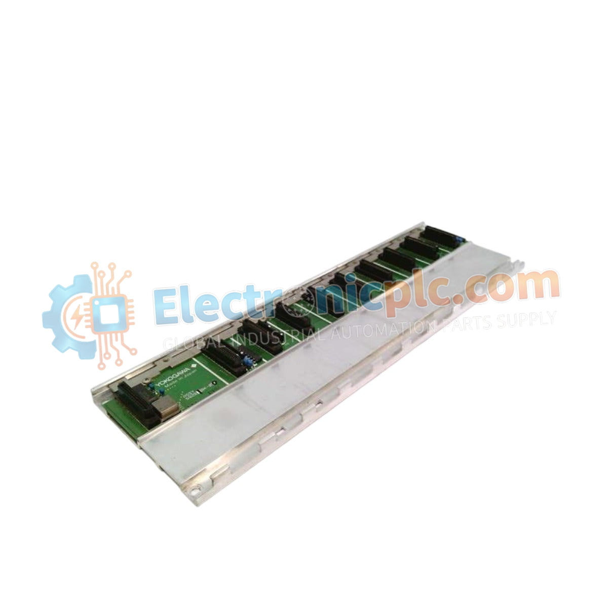
Configured for high-density module mounting in FA-M3 programmable logic controller (PLC) network platforms, the Yokogawa F3BU09-0N/D2 (F3BU09-0N/D2 Base Unit) provides direct physical/electrical execution. This 9-slot component serves as the primary F3BU09 foundation utilized to execute module retention and backplane bus communication across FA-M3V and FA-M3R controller platforms.
| Parameter | Specification |
|---|---|
| Model | F3BU09-0N/D2 |
| Brand | Yokogawa |
| Origin | Japan |
| Weight | 1.4 kg |
| Dimensions | 420 mm x 100 mm x 60 mm |
| Operating Temp | 0 to 55 deg C |
| Power Consumption | Passive bus distribution |
| Slot Capacity | 9 slots (including 1 dedicated CPU slot) |
| Mounting | DIN rail or panel mount |
The F3BU09-0N/D2 serves as the structural and electrical backbone for the FA-M3 PLC system. The backplane design ensures deterministic backplane bus communication velocity, facilitating rapid data exchange between the CPU and I/O modules. The unit is specifically engineered to accommodate double-slot modules, such as the F3PU20-0S and F3PU26-0S, providing the mechanical support and electrical pathway necessary for high-performance automation tasks. The backplane also handles power distribution from the 24 V DC supply, maintaining a stable operating voltage across the 9 slots to ensure reliable logic execution.
Q: Can the F3BU09-0N/D2 support multiple power supply units?
A: The base unit is designed to distribute power provided by a mounted power supply module. Refer to the power capacity documentation for your specific FA-M3 configuration to ensure the total power consumption of all inserted modules does not exceed the capacity of the power supply unit.
Q: Is it necessary to install dummy covers in empty slots?
A: Yes. For both mechanical protection and to maintain the airflow required for the internal components, all empty slots should be fitted with appropriate blanking plates.


