انتقل إلى معلومات المنتج
1 ل 3

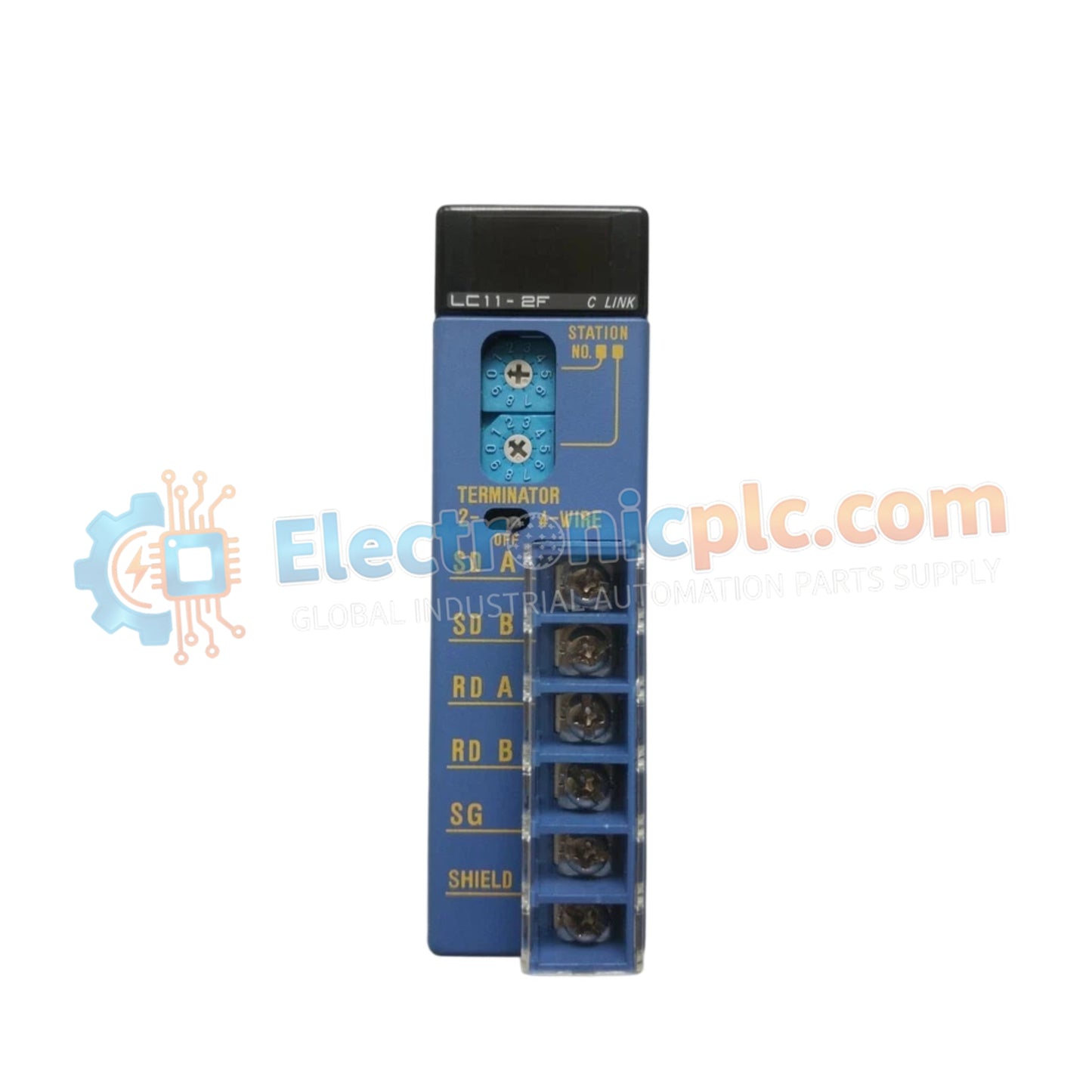
YOKOGAWA F3LC11-2F PC Link Module

YOKOGAWA F3LC11-2F PC Link Module

Configured for serial data exchange in FA-M3 control networks, the YOKOGAWA F3LC11-2F (F3LC11 PC Link Module) provides direct physical/electrical execution of protocol-based communication between controllers and external host devices.

Hardware...

22 يشاهد الناس هذا الآن

التوافرفي الأوراق المالية

رمز المنتج: F3LC11-2F
بائع: Yokogawa
فئة: PC Link Module
Related Series:

الشحن والإرجاع

توصيل موثوق به في جميع أنحاء العالم

  • شركات الشحن: يتم الشحن عبر DHL أو FedEx أو UPS أو USPS .
  • الشحن: تتم معالجة الطلبات خلال يوم عمل واحد إلى يومين، ويتم شحنها خلال 3 إلى 5 أيام عمل .
  • التتبع: يتم توفير تفاصيل التتبع الكاملة عبر البريد الإلكتروني عند الشحن.

ضمان استرداد الأموال خلال 30 يومًا

  • الضمان: فترة إرجاع لمدة 30 يومًا للمنتجات المتوفرة في المخزون والمغلفة من المصنع.
  • الشروط: يجب أن تكون المنتجات غير مفتوحة وغير مستخدمة وفي عبوتها الأصلية.
  • الأصالة: نضمن أن تكون الأجهزة أصلية 100% .

هل تحتاج إلى مزيد من التفاصيل؟ اقرأ سياسة الشحن وسياسة الاسترداد الكاملة.

الأصالة والضمان

  • ضمان أصلي: نحن نوفر فقط قطع غيار أصلية 100%، جديدة تمامًا، ومغلقة من المصنع .
  • تغطية كاملة: كل مكون مدعوم بضمان شامل لمدة 12 شهرًا من تاريخ الشراء.
  • إمكانية التتبع: جميع المنتجات تأتي مع وثائق المصنع الأصلية والملحقات اللازمة للامتثال الكامل للمعايير الصناعية.

الدعم الفني والتوريد

  • مساعدة الخبراء: يقدم فريقنا الفني استشارات مجانية لمساعدتك في التحقق من التوافق مع أنظمة DCS و PLC.
  • مصادر القطع النادرة: متخصصون في المكونات القديمة والتي يصعب العثور عليها من Allen-Bradley و Siemens و ABB و HIMA وغيرها.
  • للاستفسارات المتعلقة بالكميات الكبيرة: تواصلوا معنا على pambo@5gplc.com للحصول على أسعار الكميات الكبيرة أو عروض أسعار المشاريع المخصصة.
عرض تفاصيل المنتج الكاملة

Configured for serial data exchange in FA-M3 control networks, the YOKOGAWA F3LC11-2F (F3LC11 PC Link Module) provides direct physical/electrical execution of protocol-based communication between controllers and external host devices.

Hardware Specifications

Parameter Specification
Model F3LC11-2F
Brand YOKOGAWA
Origin Japan
Weight 0.2 kg
Dimensions Standard FA-M3 base unit module form factor
Operating Temp 0 deg C to 55 deg C
Power Consumption 0.5 A (5 V DC)
Interfaces RS-232C, RS-422A, RS-485
Baud Rate Up to 115.2 kbps
Max Connections 32 units (via RS-422A/485)

Backplane Bus Communication and Deterministic Networks

The F3LC11-2F utilizes a proprietary FA-M3 serial protocol to facilitate deterministic data exchange across the module backplane. This interface is engineered for I/O density scaling, allowing the controller to manage communication buffers without degrading scan-time performance. The module supports firmware flash compatibility to accommodate protocol updates and configuration adjustments, ensuring that the serial communication link maintains high-throughput integrity even when scaled to the maximum limit of 32 connected network nodes.

Frequently Asked Questions

Q: Can the RS-485 interface be configured for multi-drop communication?

A: Yes, the F3LC11-2F supports multi-drop configurations using the RS-422A/485 interface. Up to 32 FA-M3 units can be daisy-chained, provided that the physical layer is properly biased and terminated at both extremities of the bus.

Q: Is the communication protocol accessible to third-party SCADA software?

A: Yes, the module uses standard ASCII-based communication sequences. Third-party host devices can interface with the module by mapping register addresses according to the FA-M3 PC Link protocol memory map.

Field Installation Guidelines

  1. Power down the FA-M3 base unit before inserting the module to prevent electrical shorts on the backplane bus.
  2. Secure the module using the built-in locking mechanism to ensure stable contact with the backplane connectors.
  3. Use shielded, twisted-pair cabling for RS-422A/485 connections; ensure the shield drain wire is connected to a high-quality chassis ground to prevent common-mode noise.
  4. Configure communication parameters (baud rate, parity, and station address) using the utility software prior to full network integration.
  5. Verify that the communication LEDs (TX/RX) blink during data transmission to confirm active link state and protocol handshake completion.