
سلة التسوق الخاصة بي
0 عنصرًا
قطع غيار أصلية للأتمتة | توصيل سريع عالمي | ضمان لمدة 12 شهرًا — [احصل على عرض سعر]

تم تكوين YOKOGAWA F3LC51-2N (وحدة الاتصال F3LC51 UT Link) للاندماج السلس للأجهزة في منصات FA-M3 PLC، وتوفر تنفيذًا ماديًا/كهربائيًا مباشرًا لتبادل بيانات جهاز التحكم في درجة...
التوافر: في الأوراق المالية
توصيل موثوق به في جميع أنحاء العالم
ضمان استرداد الأموال خلال 30 يومًا
هل تحتاج إلى مزيد من التفاصيل؟ اقرأ سياسة الشحن وسياسة الاسترداد الكاملة.


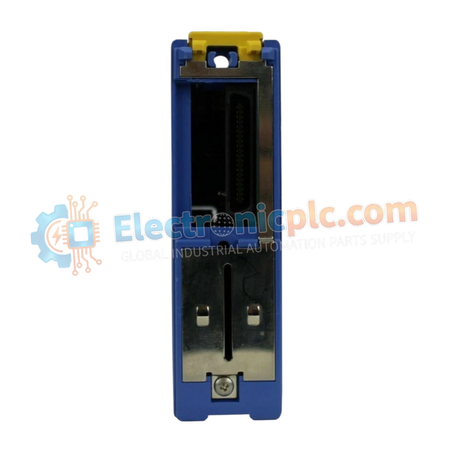
تم تكوين YOKOGAWA F3LC51-2N (وحدة الاتصال F3LC51 UT Link) للاندماج السلس للأجهزة في منصات FA-M3 PLC، وتوفر تنفيذًا ماديًا/كهربائيًا مباشرًا لتبادل بيانات جهاز التحكم في درجة الحرارة. تدير مكونات الأجهزة هذه عمليات القراءة/الكتابة التلقائية للسجلات دون الحاجة إلى برمجة اتصال مخصصة.
يتم تعريف F3LC51-2N من خلال سمات التكوين التالية:
F3: بادئة السلسلة التي تشير إلى التوافق مع بنية اللوحة الخلفية لـ Yokogawa FA-M3.
LC: تعيين وظيفة وحدة الاتصال.
51: يشير إلى الجيل المحدد لواجهة UT Link.
-2N: يحدد تكوين المنفذ ومعيار واجهة الشبكة.
| المعلمة | المواصفات |
| النموذج | F3LC51-2N |
| العلامة التجارية | YOKOGAWA |
| المنشأ | سنغافورة |
| الوزن | 0.15 كجم (0.34 رطل) |
| الأبعاد | غلاف الوحدة القياسية |
| درجة حرارة التشغيل | 0 درجة مئوية إلى 55 درجة مئوية |
| استهلاك الطاقة | 5 فولت تيار مستمر (المنطق الداخلي) |
| الحد الأقصى للمحطات المتصلة | 32 جهازًا |
| منافذ الشبكة | 1 x RS-422/RS-485 |
| أقصى طول للكابل | 1200 متر |
يستخدم F3LC51-2N سرعة اتصال ناقل اللوحة الخلفية عالية السرعة للربط بين وحدة المعالجة المركزية FA-M3 والأجهزة الميدانية الخارجية. باستخدام بروتوكولات UT Link و PC Link، تضمن الوحدة تبادلًا محددًا للبيانات، وتحديث السجلات تلقائيًا. تقلل هذه الأتمتة على مستوى الأجهزة من حمل مسح وحدة المعالجة المركزية وتضمن توقيتًا ثابتًا للبيانات لما يصل إلى 32 محطة عن بعد عبر كابلات RS-485.
س: هل يمكن تكوين F3LC51-2N للتواصل مع أدوات غير Yokogawa؟ج: تم تحسين الوحدة للأدوات المتوافقة مع UT. بينما تدعم أوامر بروتوكول PC Link القياسية، يتطلب الاتصال بأجهزة الطرف الثالث تأكيد توافق البروتوكول ومطابقة مجموعة الأوامر.
س: هل هذه الوحدة قادرة على دعم التبديل السريع على رف FA-M3؟ج: لا، لا تدعم الوحدة التبديل السريع. تأكد من فصل طاقة نظام PLC قبل تثبيت أو إزالة F3LC51-2N لتجنب التلف الكهربائي لدبابيس اللوحة الخلفية.
ثبت الوحدة بإحكام في الوحدة الأساسية FA-M3. تأكد من أن موصلات اللوحة الخلفية الخلفية متصلة بالكامل وأن مسامير التثبيت مشدودة.
بالنسبة لاتصالات RS-485/RS-422، استخدم كابلًا محميًا ومزدوجًا ملتويًا. تأكد من أن طول الكابل لا يتجاوز 1200 متر للحفاظ على سلامة الإشارة وسرعة الاتصال.
أنهي الناقل عند كلا الطرفين الماديين باستخدام مقاومات مناسبة لمطابقة مقاومة الخط ومنع انعكاسات الإشارة.
قم بتأريض درع كابل الاتصال عند نقطة واحدة لمنع حلقات الأرض، خاصة عندما يتم تشغيل الأجهزة من مصادر مختلفة.
قم بتكوين عناوين المحطة ومعلمات الاتصال على الأجهزة الميدانية المتصلة لمطابقة الإعدادات المحددة في سجلات برنامج PLC.


