انتقل إلى معلومات المنتج
1 ل 3

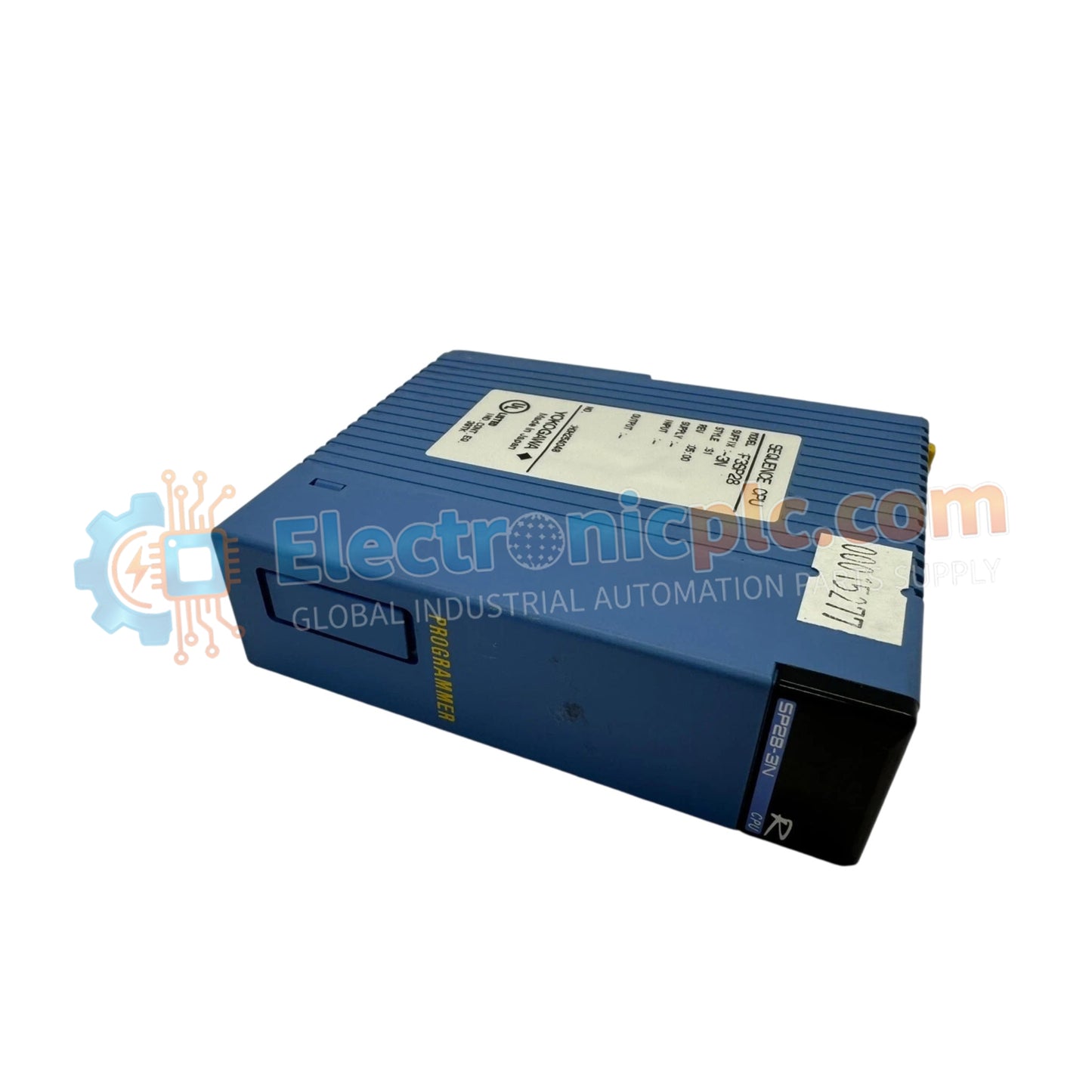
YOKOGAWA F3SP28-3N CPU Module

YOKOGAWA F3SP28-3N CPU Module

The YOKOGAWA F3SP28-3N, also cataloged as the F3SP28 CPU Module, operates as a dedicated hardware component for high-speed sequence control and ladder logic execution within FA-M3 PLC platforms.

Hardware Specifications

...
18 يشاهد الناس هذا الآن

التوافرفي الأوراق المالية

رمز المنتج: F3SP28-3N
بائع: Yokogawa
فئة: CPU Module
Related Series:

الشحن والإرجاع

توصيل موثوق به في جميع أنحاء العالم

  • شركات الشحن: يتم الشحن عبر DHL أو FedEx أو UPS أو USPS .
  • الشحن: تتم معالجة الطلبات خلال يوم عمل واحد إلى يومين، ويتم شحنها خلال 3 إلى 5 أيام عمل .
  • التتبع: يتم توفير تفاصيل التتبع الكاملة عبر البريد الإلكتروني عند الشحن.

ضمان استرداد الأموال خلال 30 يومًا

  • الضمان: فترة إرجاع لمدة 30 يومًا للمنتجات المتوفرة في المخزون والمغلفة من المصنع.
  • الشروط: يجب أن تكون المنتجات غير مفتوحة وغير مستخدمة وفي عبوتها الأصلية.
  • الأصالة: نضمن أن تكون الأجهزة أصلية 100% .

هل تحتاج إلى مزيد من التفاصيل؟ اقرأ سياسة الشحن وسياسة الاسترداد الكاملة.

الأصالة والضمان

  • ضمان أصلي: نحن نوفر فقط قطع غيار أصلية 100%، جديدة تمامًا، ومغلقة من المصنع .
  • تغطية كاملة: كل مكون مدعوم بضمان شامل لمدة 12 شهرًا من تاريخ الشراء.
  • إمكانية التتبع: جميع المنتجات تأتي مع وثائق المصنع الأصلية والملحقات اللازمة للامتثال الكامل للمعايير الصناعية.

الدعم الفني والتوريد

  • مساعدة الخبراء: يقدم فريقنا الفني استشارات مجانية لمساعدتك في التحقق من التوافق مع أنظمة DCS و PLC.
  • مصادر القطع النادرة: متخصصون في المكونات القديمة والتي يصعب العثور عليها من Allen-Bradley و Siemens و ABB و HIMA وغيرها.
  • للاستفسارات المتعلقة بالكميات الكبيرة: تواصلوا معنا على pambo@5gplc.com للحصول على أسعار الكميات الكبيرة أو عروض أسعار المشاريع المخصصة.
عرض تفاصيل المنتج الكاملة

The YOKOGAWA F3SP28-3N, also cataloged as the F3SP28 CPU Module, operates as a dedicated hardware component for high-speed sequence control and ladder logic execution within FA-M3 PLC platforms.

Hardware Specifications

Parameter Specification
Model F3SP28-3N
Brand YOKOGAWA
Origin Japan
Weight 0.15 kg
Dimensions 28.9 mm x 100 mm x 83.2 mm
Operating Temp 0 deg C to 55 deg C
Power Consumption 0.5 A (5 V DC)
Program Capacity 30K steps
Processing Speed 0.045 us (Basic instruction)
I/O Capacity 4096 points

Backplane Bus Communication and Deterministic Networks

The F3SP28-3N manages internal backplane bus communication velocity to ensure deterministic execution of ladder logic control. The architecture supports I/O density scaling up to 4096 points, allowing the processor to handle extensive process data without exceeding the 1 ms scan time for 6K steps. The module architecture includes firmware flash compatibility to support updates to the instruction set and network communication stack, ensuring that the controller remains synchronized with field-level protocols and external SCADA interface requirements.

Frequently Asked Questions

Q: Can the instruction processing speed be optimized for specific application requirements?

A: The processor executes instructions at a fixed rate of 0.045 us per basic instruction. System scan time is primarily dependent on the total number of ladder logic steps and the density of I/O points configured on the backplane.

Q: How is the built-in memory protected against power loss?

A: The module utilizes non-volatile memory for program storage. Ensure that the internal backup battery is replaced according to the manufacturer recommended service interval to maintain data retention for volatile register values during extended power outages.

Field Installation Guidelines

  1. Power down the FA-M3 base unit before inserting the CPU module into the primary controller slot.
  2. Ensure the module is seated fully into the backplane; improper seating can lead to intermittent bus communication or complete CPU failure to initialize.
  3. Configure Ethernet and serial communication ports via the engineering workstation prior to full system integration.
  4. Verify that the module RUN/STOP switch is correctly positioned based on the desired operational mode for the PLC.
  5. Confirm that the status LED indicators show "RUN" mode stability after the diagnostic boot sequence has completed.