سلة التسوق الخاصة بي
0 عنصرًا
قطع غيار أصلية للأتمتة | توصيل سريع عالمي | ضمان لمدة 12 شهرًا — [احصل على عرض سعر]

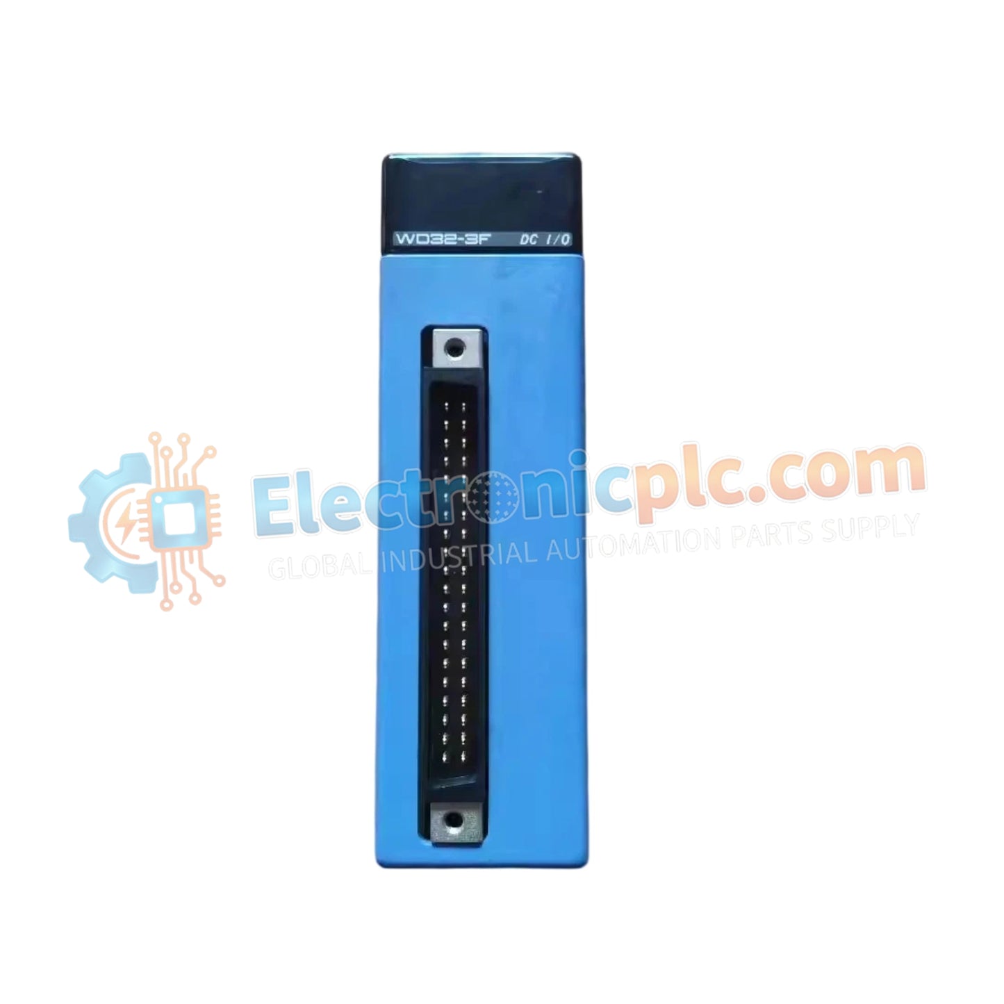
تعمل وحدة الإدخال/الإخراج YOKOGAWA F3WD32-3F، والمصنفة أيضًا باسم F3WD32، كمكون مادي مخصص لاكتساب الإشارة المنفصلة ضمن منصات PLC من طراز FA-M3.
| المعلمة | المواصفات | ...
|---|
| المعلمة | المواصفات |
|---|---|
| النموذج | F3WD32-3F |
| العلامة التجارية | YOKOGAWA |
| المنشأ | اليابان |
| الوزن | 0.14 كجم |
| الأبعاد | 28.9 ملم × 100 ملم × 83.2 ملم |
| درجة حرارة التشغيل | من 0 درجة مئوية إلى 55 درجة مئوية |
| استهلاك الطاقة | 0.25 أمبير (5 فولت تيار مستمر) |
| نوع الإدخال/الإخراج | مدخل رقمي |
| عدد القنوات | 32 |
| المدخل المقنن | 24 فولت تيار مستمر |
تتكامل الوحدة F3WD32-3F مباشرة مع اللوحة الخلفية FA-M3، وتستخدم اتصال ناقل عالي السرعة لربط 32 نقطة من بيانات الإدخال المنفصلة بمساحة ذاكرة وحدة المعالجة المركزية. تم تصميم بنية الوحدة لتمكين توسيع كثافة الإدخال/الإخراج بكفاءة، مما يسمح لوحدة التحكم بإدارة تكوينات ذات عدد قنوات عالٍ مع الحفاظ على أداء وقت المسح المحدد. يتم دعم توافق تحديثات البرامج الثابتة (Firmware flash)، مما يسمح بتحديث منطق الوحدة ليظل متوافقًا مع مراجعات البرامج الثابتة PLC على مستوى النظام ومتطلبات الاتصال بالشبكة.
س: هل تدعم الوحدة التبديل السريع (hot-swapping) في وحدة قاعدة FA-M3 نشطة؟
ج: لا، لا تدعم الوحدة التبديل السريع. يجب فصل الطاقة عن الوحدة الأساسية قبل إدخال الوحدة أو إزالتها لمنع حدوث تلف كهربائي لدبابيس اللوحة الخلفية أو دوائر المنطق.
س: كيف يتم التحقق من حالة منطق الإدخال أثناء تشغيل النظام؟
ج: تتميز اللوحة الأمامية للوحدة بمؤشرات LED تتوافق مباشرة مع حالة كل قناة إدخال. تأكد من تطبيق جهد المجال 24 فولت تيار مستمر بشكل صحيح؛ سيضيء مؤشر LED المقابل عندما يتم تنشيط دائرة الإدخال.