
سلة التسوق الخاصة بي
0 عنصرًا
قطع غيار أصلية للأتمتة | توصيل سريع عالمي | ضمان لمدة 12 شهرًا — [احصل على عرض سعر]

تعمل YOKOGAWA F3WD64-3P (وحدة الإدخال/الإخراج الرقمي F3WD64) كمكون مادي مخصص لمعالجة الإشارة المختلطة ضمن منصات وحدة التحكم المنطقية القابلة للبرمجة FA-M3. توفر هذه الوحدة تنفيذًا ماديًا/كهربائيًا مباشرًا لـ 32 مدخلاً...
التوافر: في الأوراق المالية
توصيل موثوق به في جميع أنحاء العالم
ضمان استرداد الأموال خلال 30 يومًا
هل تحتاج إلى مزيد من التفاصيل؟ اقرأ سياسة الشحن وسياسة الاسترداد الكاملة.


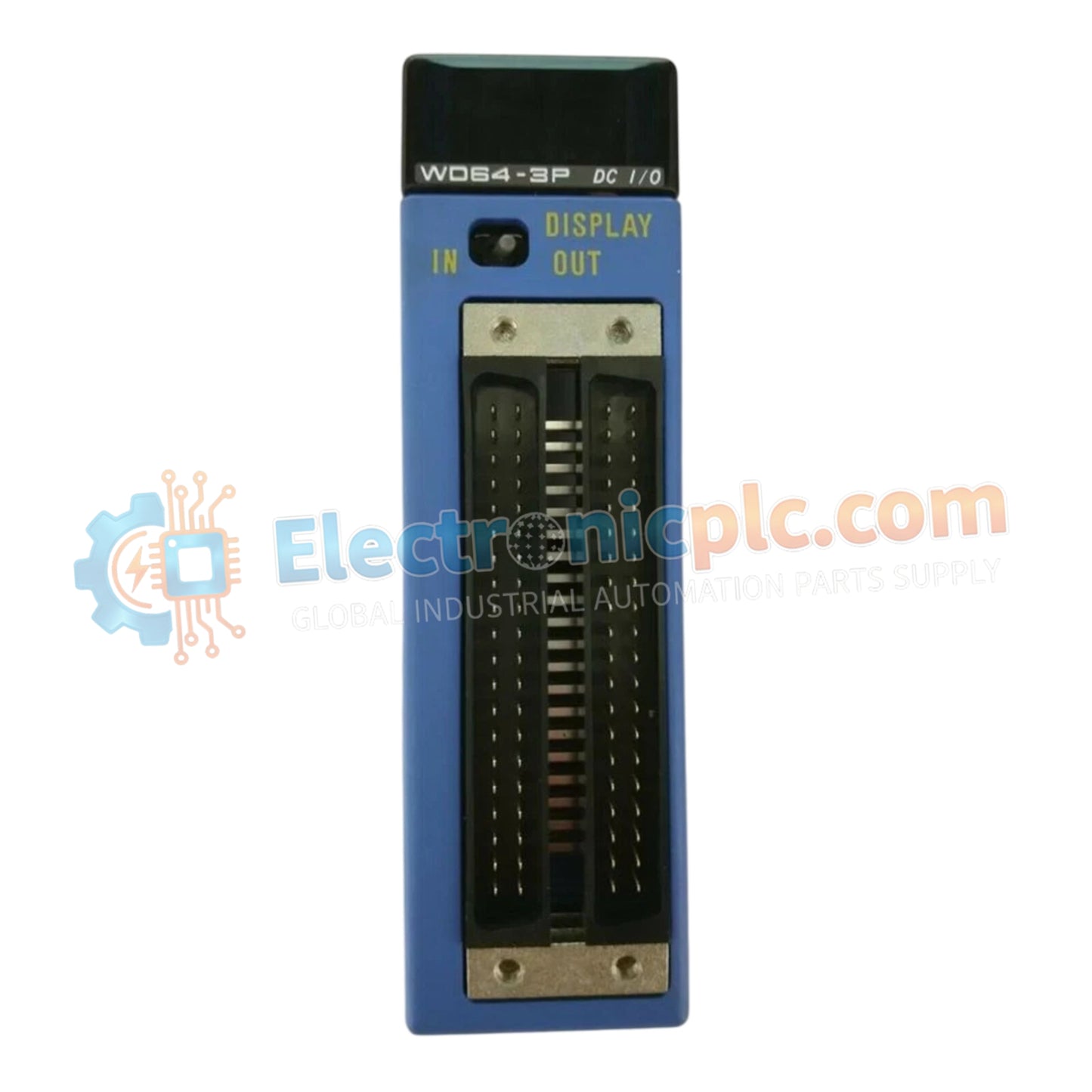
تعمل YOKOGAWA F3WD64-3P (وحدة الإدخال/الإخراج الرقمي F3WD64) كمكون مادي مخصص لمعالجة الإشارة المختلطة ضمن منصات وحدة التحكم المنطقية القابلة للبرمجة FA-M3. توفر هذه الوحدة تنفيذًا ماديًا/كهربائيًا مباشرًا لـ 32 مدخلاً رقميًا و32 مخرجًا متصلًا بترانزستور، مما يسهل التكامل عالي الكثافة للتحكم في بيئات الأتمتة الصناعية.
يتم تحديد F3WD64-3P من خلال سمات التكوين التالية:
F3: بادئة السلسلة التي تشير إلى التوافق مع بنية اللوحة الخلفية Yokogawa FA-M3.
WD: وظيفة هجينة للإدخال/الإخراج الرقمي.
64: سعة إجمالية للإدخال/الإخراج تبلغ 64 نقطة (32 مدخلًا / 32 مخرجًا).
3P: تكوين مخرج متصل بترانزستور مع توافق جهد تشغيل 24 فولت تيار مستمر/12 فولت تيار مستمر.
| المعلمة | المواصفة |
| النموذج | F3WD64-3P |
| العلامة التجارية | YOKOGAWA |
| المنشأ | اليابان |
| قنوات الإدخال | 32 (معزولة بالضوء) |
| قنوات الإخراج | 32 (نوع الترانزستور المتصل) |
| جهد التشغيل | 24 فولت تيار مستمر (20.4–26.4 فولت) / 12 فولت تيار مستمر (10.2–13.2 فولت) |
| تيار الإدخال | 4.1 مللي أمبير لكل نقطة |
| العزل | بالضوء |
| التركيب | رف FA-M3 |
تستخدم F3WD64-3P اتصالات ناقل اللوحة الخلفية عالية السرعة للربط بين الأجهزة الميدانية ومنطق وحدة التحكم FA-M3. أوقات أخذ عينات الإدخال قابلة للتكوين، مما يسمح بتحكم دقيق في فترات الاستجابة من 0 ميكروثانية إلى 1 مللي ثانية. يضمن هذا الأداء الحتمي التقاط التغييرات في الحالة وعكسها بدقة في ذاكرة PLC، مع الحفاظ على التزامن عبر تسلسلات التحكم المعقدة دون تأخير في مسح وحدة المعالجة المركزية.
س: هل يمكن لقنوات الإخراج التعامل مع الأحمال الاستقرائية مباشرة؟
ج: تتطلب مخارج الترانزستور المتصلة (sink outputs) صمامات ثنائية خارجية لمنع التدفق العكسي (flyback diodes) عند تشغيل الأحمال الاستقرائية (مثل صمامات الملف اللولبي أو المرحلات) لقمع ارتفاعات الجهد التي قد تلحق الضرر بترانزستورات الإخراج الداخلية.
س: هل من الممكن استخدام خطوط مشتركة مختلفة لمجموعات مختلفة من المدخلات؟
ج: تستخدم بنية الوحدة هيكل خط مشترك من 8 نقاط لكل خط مشترك لكل من المدخلات والمخرجات. يجب التأكد من أن الجهد المرجعي لكل مجموعة من 8 قنوات متوافق مع نطاق جهد تشغيل الوحدة.
تأكد من أن مصدر الطاقة ضمن النطاق المحدد من 10.2 فولت تيار مستمر إلى 26.4 فولت تيار مستمر بناءً على متطلبات التطبيق قبل التوصيل بالكتلة الطرفية.
التزم بمتطلبات نسبة "تشغيل" الإدخال المتزامن القصوى البالغة 60% لإدارة تبديد الطاقة ومنع الحمل الحراري الزائد داخل غلاف الوحدة.
استخدم الكابلات المحمية لإشارات الإدخال، خاصة تلك التي يتم توجيهها بالقرب من مصادر الضوضاء العالية مثل كابلات محركات التردد المتغير (VFD)، وقم بتوصيل الدرع بنقطة التأريض الواقية للخزانة.
تحقق من قطبية توصيل النوع المتصل (sink-type wiring)؛ يجب توصيل المشترك الناتج بالجانب السالب لمصدر الطاقة 24 فولت تيار مستمر أو 12 فولت تيار مستمر لضمان التبديل الصحيح للحمل.
بعد التوصيل، استخدم برنامج تهيئة PLC لتعيين بتات الإدخال والإخراج المحددة والتحقق من الوظائف من خلال اختبار فرض الحالة اليدوي قبل التكامل الكامل للنظام.


