انتقل إلى معلومات المنتج
1 ل 3

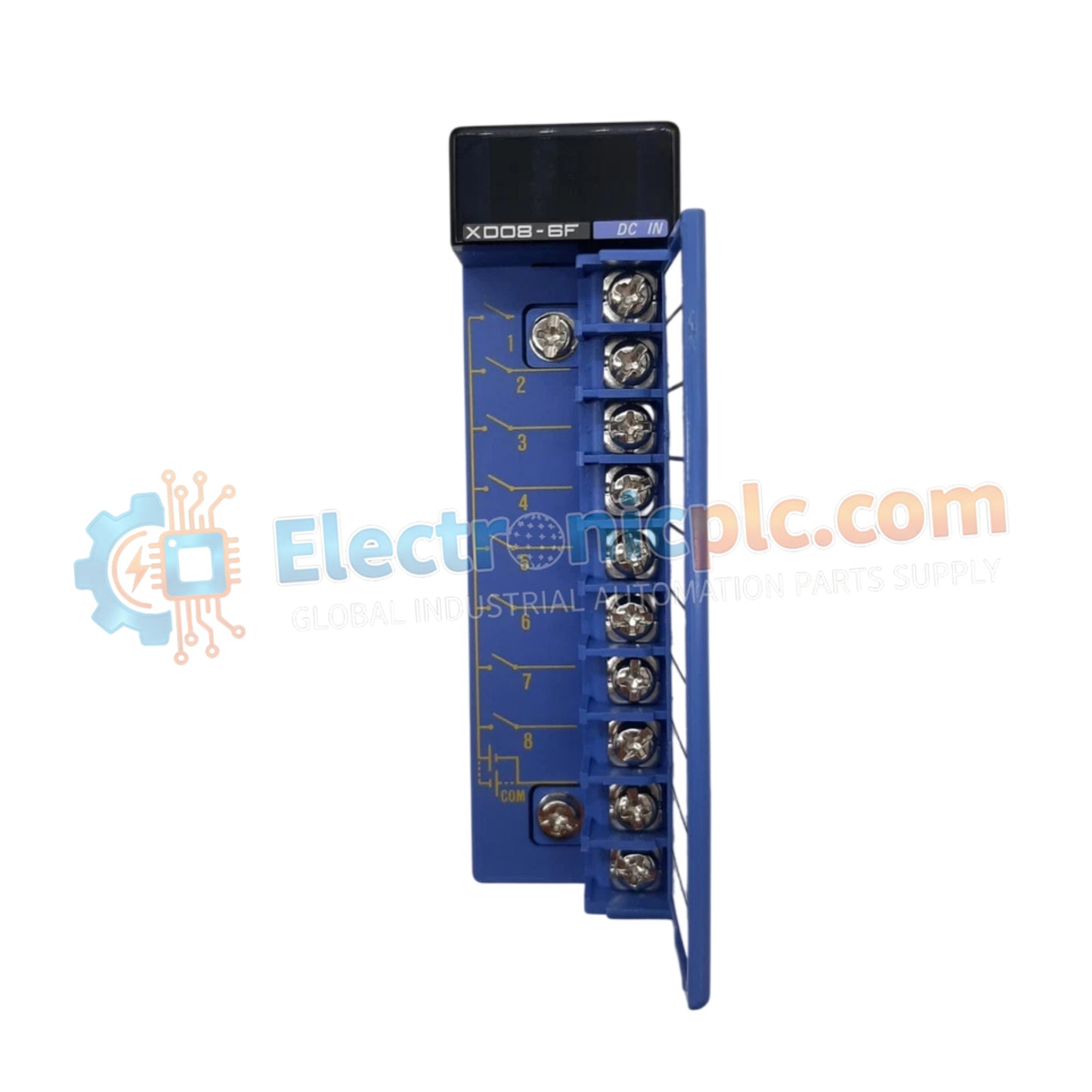
Yokogawa F3XD08-6F Digital Input/Output Module

Yokogawa F3XD08-6F Digital Input/Output Module

Configured for mixed signal processing in FA-M3 control networks, the Yokogawa F3XD08-6F (F3XD08-6F Digital I/O Module) provides direct physical/electrical execution of 8-channel digital input and 8-channel digital output monitoring.

Suffix...

27 يشاهد الناس هذا الآن

التوافرفي الأوراق المالية

رمز المنتج: F3XD08-6F
بائع: Yokogawa

الشحن والإرجاع

توصيل موثوق به في جميع أنحاء العالم

  • شركات الشحن: يتم الشحن عبر DHL أو FedEx أو UPS أو USPS .
  • الشحن: تتم معالجة الطلبات خلال يوم عمل واحد إلى يومين، ويتم شحنها خلال 3 إلى 5 أيام عمل .
  • التتبع: يتم توفير تفاصيل التتبع الكاملة عبر البريد الإلكتروني عند الشحن.

ضمان استرداد الأموال خلال 30 يومًا

  • الضمان: فترة إرجاع لمدة 30 يومًا للمنتجات المتوفرة في المخزون والمغلفة من المصنع.
  • الشروط: يجب أن تكون المنتجات غير مفتوحة وغير مستخدمة وفي عبوتها الأصلية.
  • الأصالة: نضمن أن تكون الأجهزة أصلية 100% .

هل تحتاج إلى مزيد من التفاصيل؟ اقرأ سياسة الشحن وسياسة الاسترداد الكاملة.

الأصالة والضمان

  • ضمان أصلي: نحن نوفر فقط قطع غيار أصلية 100%، جديدة تمامًا، ومغلقة من المصنع .
  • تغطية كاملة: كل مكون مدعوم بضمان شامل لمدة 12 شهرًا من تاريخ الشراء.
  • إمكانية التتبع: جميع المنتجات تأتي مع وثائق المصنع الأصلية والملحقات اللازمة للامتثال الكامل للمعايير الصناعية.

الدعم الفني والتوريد

  • مساعدة الخبراء: يقدم فريقنا الفني استشارات مجانية لمساعدتك في التحقق من التوافق مع أنظمة DCS و PLC.
  • مصادر القطع النادرة: متخصصون في المكونات القديمة والتي يصعب العثور عليها من Allen-Bradley و Siemens و ABB و HIMA وغيرها.
  • للاستفسارات المتعلقة بالكميات الكبيرة: تواصلوا معنا على pambo@5gplc.com للحصول على أسعار الكميات الكبيرة أو عروض أسعار المشاريع المخصصة.
عرض تفاصيل المنتج الكاملة

Configured for mixed signal processing in FA-M3 control networks, the Yokogawa F3XD08-6F (F3XD08-6F Digital I/O Module) provides direct physical/electrical execution of 8-channel digital input and 8-channel digital output monitoring.

Suffix Breakdown & Model Matrix

  • F3XD08-6F: Base module designation for an 8-point digital input and 8-point digital output combined unit, supporting sink/source logic configurations.

Hardware Specifications

Parameter Specification
Model F3XD08-6F
Brand Yokogawa
Origin japan
Weight 0.2kg
Dimensions 100 mm x 110 mm x 30 mm
Operating Temp 0 deg C to 55 deg C
Power Consumption Not Specified
Input Points 8 points (12-24 VDC)
Output Points 8 points (24 VDC, 0.5 A)
Input Current 4.1 mA (12 VDC), 8.5 mA (24 VDC)
Response Time OFF to ON: 100 us; ON to OFF: 300 us

Industrial Control and I/O Density Scaling

The F3XD08-6F module integrates high-speed signal switching within the FA-M3 series architecture. The internal design utilizes photocoupler isolation to decouple field-side logic from the processor backplane, preventing electrical noise from impacting backplane bus communication velocity. The module supports flexible I/O density scaling, allowing for deterministic interaction with field sensors and actuators while maintaining compatibility with industry-standard DIN rail mounting configurations. This electrical isolation ensures that high-speed response times are preserved across the digital loop during active process monitoring.

Frequently Asked Questions

Q: Does the F3XD08-6F module support hot-swapping while the base unit is energized?

A: No. The F3XD08-6F is not rated for hot-swapping. Ensure the PLC system power is disconnected from the base unit prior to module installation or removal to prevent potential damage to the internal logic circuits.

Q: Can the input type be switched between sink and source modes on a per-point basis?

A: The input circuitry supports sink/source logic, but configuration must be verified against the specific wiring diagram provided in the user manual to ensure compatibility with field-connected sensors.

Field Installation Guidelines

  1. Mount the module on a standard DIN rail, ensuring the locking mechanism is fully engaged to prevent mechanical vibration impacts.
  2. Verify that field supply voltages for inputs are within the 10.2-26.4 VDC operating range before enabling the loop.
  3. Ensure the 0.5 A output current limit per point is not exceeded to avoid thermal overload of the internal output transistors.
  4. Route signal cables in dedicated wireways, keeping them separated from high-voltage AC cabling to maintain the integrity of the photocoupler isolation.
  5. Confirm that all terminal wiring is secure and that no bare wire strands are exposed, which could cause short circuits within the high-density terminal block.