سلة التسوق الخاصة بي
0 عنصرًا
قطع غيار أصلية للأتمتة | توصيل سريع عالمي | ضمان لمدة 12 شهرًا — [احصل على عرض سعر]

The Yokogawa KS1-20 B, also cataloged as the KS1-20 B Signal Cable, operates as a dedicated hardware component for signal transmission between process control interface modules and field termination assemblies...
التوافر: في الأوراق المالية
توصيل موثوق به في جميع أنحاء العالم
ضمان استرداد الأموال خلال 30 يومًا
هل تحتاج إلى مزيد من التفاصيل؟ اقرأ سياسة الشحن وسياسة الاسترداد الكاملة.


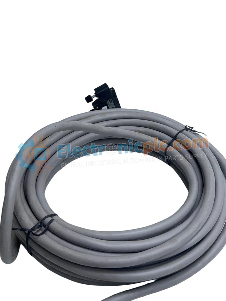
The Yokogawa KS1-20 B, also cataloged as the KS1-20 B Signal Cable, operates as a dedicated hardware component for signal transmission between process control interface modules and field termination assemblies within Yokogawa DCS platforms.
| Parameter | Specification |
|---|---|
| Model | KS1-20 B |
| Brand | Yokogawa |
| Origin | Japan |
| Weight | 0.9 kg |
| Dimensions | 25.4 x 5.1 x 38.1 cm |
| Operating Temp | Standard industrial ambient |
| Power Consumption | Passive cabling component |
The KS1-20 B serves as a high-density interconnection cable designed to maintain channel-to-channel isolation requirements across instrumentation loops. The cable assembly is engineered to facilitate precise data transit while minimizing electromagnetic interference (EMI) and crosstalk within the cabinet environment. By utilizing specialized shielding configurations, this cable ensures that 4-20 mA analog signals and discrete I/O communications remain stable across the distance between the controller base plates and field junction points. The physical construction is optimized to maintain low impedance and structural integrity under standard industrial operating conditions.
Q: Are there specific installation requirements for the cable shielding?
A: Yes. The shield should be grounded at the designated common ground point of the termination assembly to effectively divert induced noise to the system earth.
Q: Is this cable suitable for use in high-vibration areas?
A: The KS1-20 B is designed for fixed installation within control cabinets. If used in areas subject to significant vibration, ensure the cable is properly supported with cable ties or conduits to prevent mechanical stress on the connector housing.


