انتقل إلى معلومات المنتج
1 ل 3

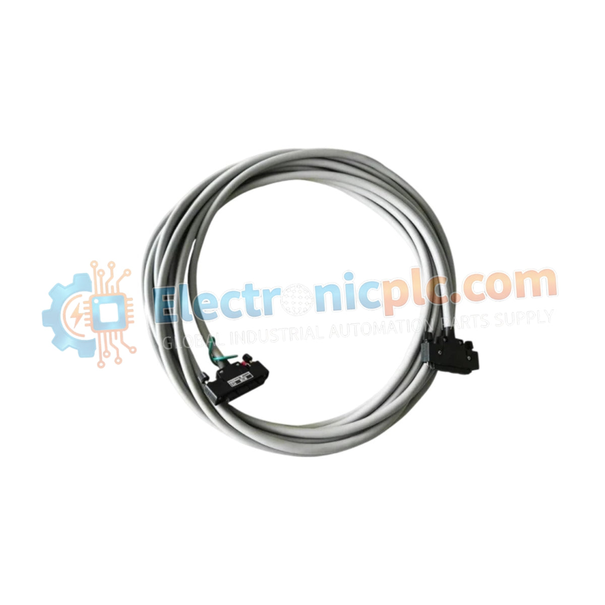
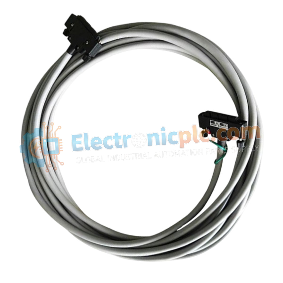
Yokogawa KS1-35 Signal Cable

Yokogawa KS1-35 Signal Cable

Configured for high-density I/O connectivity within CENTUM and FCN/FCJ controller platforms, the Yokogawa KS1-35 (KS1-35 Signal Cable) provides direct physical and electrical execution of multi-point signal transmission between field termination...

16 يشاهد الناس هذا الآن

التوافرفي الأوراق المالية

رمز المنتج: KS1-35
بائع: Yokogawa
فئة: Signal Cable
Related Series:

الشحن والإرجاع

توصيل موثوق به في جميع أنحاء العالم

  • شركات الشحن: يتم الشحن عبر DHL أو FedEx أو UPS أو USPS .
  • الشحن: تتم معالجة الطلبات خلال يوم عمل واحد إلى يومين، ويتم شحنها خلال 3 إلى 5 أيام عمل .
  • التتبع: يتم توفير تفاصيل التتبع الكاملة عبر البريد الإلكتروني عند الشحن.

ضمان استرداد الأموال خلال 30 يومًا

  • الضمان: فترة إرجاع لمدة 30 يومًا للمنتجات المتوفرة في المخزون والمغلفة من المصنع.
  • الشروط: يجب أن تكون المنتجات غير مفتوحة وغير مستخدمة وفي عبوتها الأصلية.
  • الأصالة: نضمن أن تكون الأجهزة أصلية 100% .

هل تحتاج إلى مزيد من التفاصيل؟ اقرأ سياسة الشحن وسياسة الاسترداد الكاملة.
الأصالة والضمان

  • ضمان أصلي: نحن نوفر فقط قطع غيار أصلية 100%، جديدة تمامًا، ومغلقة من المصنع .
  • تغطية كاملة: كل مكون مدعوم بضمان شامل لمدة 12 شهرًا من تاريخ الشراء.
  • إمكانية التتبع: جميع المنتجات تأتي مع وثائق المصنع الأصلية والملحقات اللازمة للامتثال الكامل للمعايير الصناعية.

الدعم الفني والتوريد

  • مساعدة الخبراء: يقدم فريقنا الفني استشارات مجانية لمساعدتك في التحقق من التوافق مع أنظمة DCS و PLC.
  • مصادر القطع النادرة: متخصصون في المكونات القديمة والتي يصعب العثور عليها من Allen-Bradley و Siemens و ABB و HIMA وغيرها.
  • للاستفسارات المتعلقة بالكميات الكبيرة: تواصلوا معنا على pambo@5gplc.com للحصول على أسعار الكميات الكبيرة أو عروض أسعار المشاريع المخصصة.
عرض تفاصيل المنتج الكاملة

Configured for high-density I/O connectivity within CENTUM and FCN/FCJ controller platforms, the Yokogawa KS1-35 (KS1-35 Signal Cable) provides direct physical and electrical execution of multi-point signal transmission between field termination assemblies and DCS/PLC backplanes.

Suffix Breakdown & Model Matrix

  • KS1: Base series designation for Yokogawa signal cable assemblies used in industrial process control.
  • 35: Represents the configuration identifier for specific pin-mapping and cable assembly length requirements.

Hardware Specifications

Parameter Specification
Model KS1-35
Brand Yokogawa
Origin Japan
Weight 0.8 kg (approximate)
Dimensions Standard industrial length (varied per order)
Operating Temp -20 deg C to 70 deg C
Power Consumption Not applicable (Passive component)
Connector Type High-density multi-pin interface
Shielding EMI-resistant braided shield

Signal Integrity and EMI Mitigation

The KS1-35 is engineered to maintain data integrity across high-density I/O arrays. The cable utilizes a multi-conductor structure with individual twist-pairing to minimize crosstalk between adjacent analog and digital signal channels. The high-coverage braided shielding effectively suppresses electromagnetic interference (EMI) generated by surrounding variable frequency drives and high-voltage power distribution infrastructure.

Frequently Asked Questions

Q: Is the KS1-35 compatible with both analog and digital I/O modules?

A: Yes. The KS1-35 is a passive transmission medium designed for use with both analog (4-20 mA) and digital (24 V DC) I/O modules, provided the terminal board pinout corresponds to the KS1 series standard.

Q: Can this cable be used in high-temperature environments?

A: The cable is rated for operation up to 70 deg C. In environments exceeding this threshold, the PVC jacket may undergo thermal degradation, leading to insulation failure. Use heat-resistant protective conduit if routing near steam piping or high-heat process equipment.

Field Installation Guidelines

  • Bending Constraints: Maintain a minimum bending radius of at least 10 times the outer diameter of the cable. Excessive bending stresses the internal conductor terminations and can degrade signal shielding continuity.
  • Connector Engagement: Verify that the multi-pin connector is fully seated and the locking mechanisms are engaged. Improper seating is the primary cause of intermittent I/O communication faults in high-density backplanes.
  • Grounding: Terminate the cable shield drain wire at the designated instrument grounding lug on the terminal assembly. Ensure the chassis ground has a low-impedance path to the primary plant earth to maximize EMI protection.
  • Routing: Segregate the KS1-35 from power cabling. Maintain a minimum separation distance of 300 mm from high-voltage AC lines to prevent inductive noise coupling.