سلة التسوق الخاصة بي
0 عنصرًا
قطع غيار أصلية للأتمتة | توصيل سريع عالمي | ضمان لمدة 12 شهرًا — [احصل على عرض سعر]

The Yokogawa KS1*B-10 B, also cataloged as the KS1*B-10 B Signal Conditioning Module, operates as a dedicated hardware component for analog signal conversion and loop isolation within process control systems.
...التوافر: الكمية المتبقية: 99
توصيل موثوق به في جميع أنحاء العالم
ضمان استرداد الأموال خلال 30 يومًا
هل تحتاج إلى مزيد من التفاصيل؟ اقرأ سياسة الشحن وسياسة الاسترداد الكاملة.
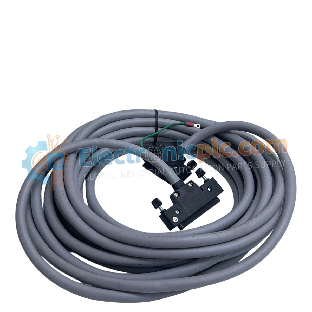

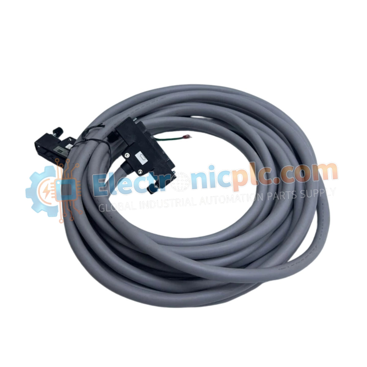
The Yokogawa KS1*B-10 B, also cataloged as the KS1*B-10 B Signal Conditioning Module, operates as a dedicated hardware component for analog signal conversion and loop isolation within process control systems.
| Parameter | Specification |
|---|---|
| Model | KS1*B-10 B |
| Brand | Yokogawa |
| Origin | Japan |
| Weight | 0.5 kg |
| Dimensions | 100 mm x 120 mm x 30 mm |
| Operating Temp | -20 deg C to +60 deg C |
| Power Consumption | +24 VDC (+/- 10%) |
| Input Signal Types | 0-10 V, -10 to +10 V, 4-20 mA, 0-20 mA |
| Output Signal | Standardized analog current or voltage |
| Input Impedance | High impedance (voltage mode) |
The module architecture provides channel-to-channel isolation to prevent ground loop interference when interfacing disparate field instruments with the control system. Utilizing high-precision circuitry, the device ensures linear conversion of process variables, maintaining signal integrity across the designated input ranges. Internal thermal management supports operation within the specified ambient temperature envelope without degradation of accuracy. The design facilitates seamless integration into DCS architectures where 4-20 mA HART loop protocol connectivity is required for instrument diagnostics and monitoring.
Q: What are the input signal limits for the voltage and current ranges?
A: The module supports voltage inputs of 0-10 V and -10 to +10 V, with high input impedance to reduce loading errors. Current inputs are compatible with 4-20 mA and 0-20 mA loops.
Q: Is this module capable of cold junction compensation (CJC)?
A: This model is designed for standard voltage and current signal conditioning and does not incorporate CJC features, which are typically found in dedicated thermocouple input modules.


