
سلة التسوق الخاصة بي
0 عنصرًا
قطع غيار أصلية للأتمتة | توصيل سريع عالمي | ضمان لمدة 12 شهرًا — [احصل على عرض سعر]

يعمل YOKOGAWA KS10-07*A، والمُدرَج أيضًا في الكتالوج باسم كابل الإشارة KS10، كمكون مادي مخصص لنقل الإشارات عالية الكثافة بين وحدات واجهة المجال وأنظمة الإدخال/الإخراج الفرعية ضمن منصات التحكم الموزعة CENTUM...
التوافر: في الأوراق المالية
توصيل موثوق به في جميع أنحاء العالم
ضمان استرداد الأموال خلال 30 يومًا
هل تحتاج إلى مزيد من التفاصيل؟ اقرأ سياسة الشحن وسياسة الاسترداد الكاملة.
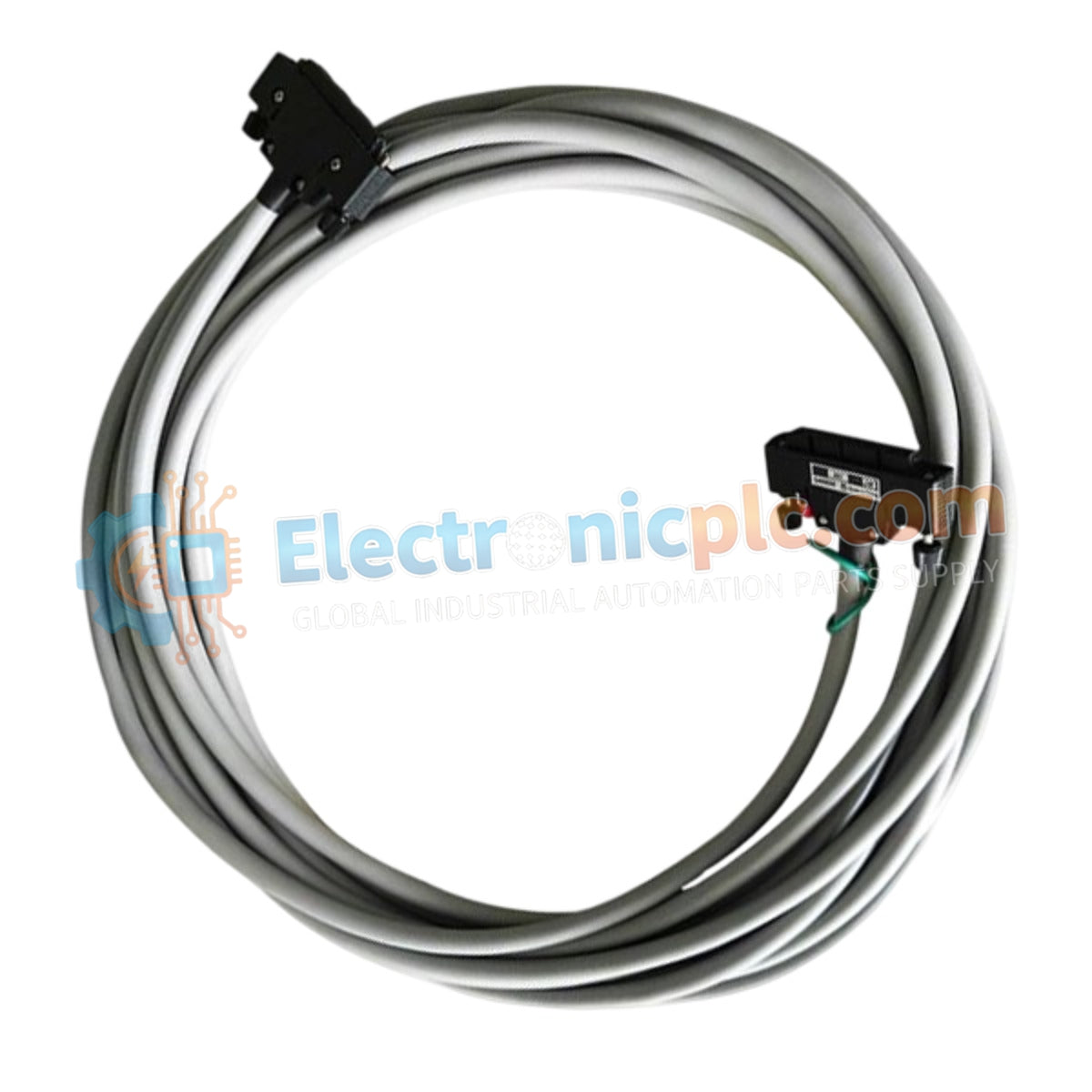
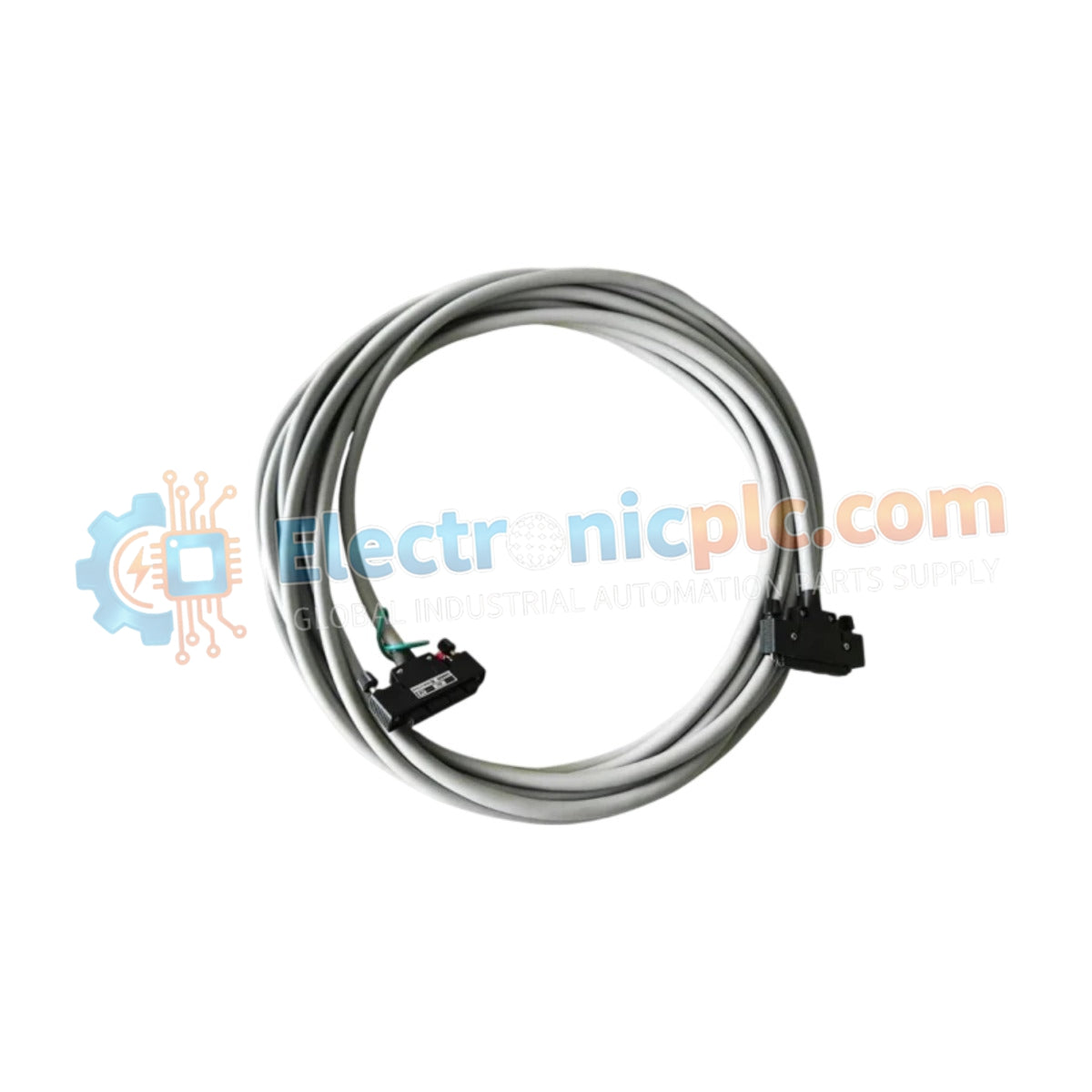
يعمل YOKOGAWA KS10-07*A، والمُدرَج أيضًا في الكتالوج باسم كابل الإشارة KS10، كمكون مادي مخصص لنقل الإشارات عالية الكثافة بين وحدات واجهة المجال وأنظمة الإدخال/الإخراج الفرعية ضمن منصات التحكم الموزعة CENTUM VP و CS3000.
| النموذج | اللاحقة / رمز النمط | الوصف |
|---|---|---|
| KS10 | 07 | طول الكابل 7 أمتار |
| KS10 | *A | النمط A |
| المعلمة | المواصفات |
|---|---|
| النموذج | KS10-07*A |
| العلامة التجارية | YOKOGAWA |
| الأصل | اليابان |
| الوزن | 1.5 كجم |
| الأبعاد | طول 7 أمتار |
| درجة حرارة التشغيل | -10 درجة مئوية إلى 60 درجة مئوية |
| استهلاك الطاقة | غير متوفر (ربط سلبي) |
| نوع الموصل | 50-دبوس إلى 50-دبوس |
| جهد التشغيل | 30 فولت تيار مستمر |
تستخدم مجموعة KS10-07*A غطاءً محميًا قويًا ضد EMI/RFI للحفاظ على دقة الإشارة في البيئات الصناعية عالية الكثافة الكهربائية. تم توصيل ترتيب الموصل الداخلي ذي 50 دبوسًا خصيصًا لدعم متطلبات الواجهة لبطاقات الإدخال/الإخراج من سلسلة CENTUM، مما يقلل من التداخل والضعف في الإشارة عبر امتداد 7 أمتار. من خلال الحفاظ على مقاومة متحكم بها وتأريض الدرع المناسب، يمنع الكابل دخول الضوضاء الخارجية، مما يضمن بقاء الإشارات التناظرية والرقمية ضمن مستويات تفاوت دقيقة أثناء عمليات نظام التحكم الموزع (DCS) في الوقت الفعلي.
س: هل هذا الكابل مناسب للاستخدام في البيئات ذات التداخل الكهرومغناطيسي العالي؟
ج: نعم، تم تصميم الدرع المدمج للحماية من EMI/RFI لتخفيف الضوضاء الخارجية. تأكد من توجيه الكابل عبر مسارات أدوات مخصصة وأن سلك تصريف الدرع متصل بشكل صحيح بهيكل النظام الأرضي لزيادة الحماية.
س: هل يمكن استخدام KS10-07*A كبديل لرموز أنماط مختلفة؟
ج: لا. غالبًا ما تشير رموز الأنماط (مثل *A مقابل *B) إلى مراجعات أسلاك أو ميكانيكية محددة فريدة لواجهة الوحدة النمطية. تحقق من وثائق النظام لوحدة الإدخال/الإخراج المستهدفة للتأكد من أن توزيع دبابيس KS10-07*A متوافق مع تعيين الطرف المطلوب.


