سلة التسوق الخاصة بي
0 عنصرًا
قطع غيار أصلية للأتمتة | توصيل سريع عالمي | ضمان لمدة 12 شهرًا — [احصل على عرض سعر]

Configured for modular signal routing and power distribution within control architectures, the Yokogawa NC1B10 (NC1B10 PLC Backplane) provides direct mechanical and electrical execution for up to 10 PLC module segments.
...التوافر: في الأوراق المالية
توصيل موثوق به في جميع أنحاء العالم
ضمان استرداد الأموال خلال 30 يومًا
هل تحتاج إلى مزيد من التفاصيل؟ اقرأ سياسة الشحن وسياسة الاسترداد الكاملة.


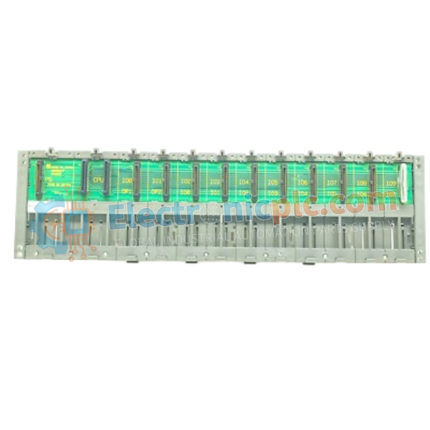
Configured for modular signal routing and power distribution within control architectures, the Yokogawa NC1B10 (NC1B10 PLC Backplane) provides direct mechanical and electrical execution for up to 10 PLC module segments.
| Parameter | Specification |
|---|---|
| Model | NC1B10 |
| Brand | Yokogawa |
| Origin | Japan |
| Weight | 0.6 kg |
| Dimensions | 17.8 cm x 0.8 cm x 13.5 cm |
| Operating Temp | -10 deg C to +55 deg C |
| Power Consumption | Passive distribution |
| Slot Capacity | 10 slots |
| Compatibility | FA-M3, STARDOM series |
| Mounting Type | DIN-rail or panel mount |
The NC1B10 architecture facilitates deterministic communication between the CPU and attached I/O modules, ensuring stable backplane bus communication velocity for high-density industrial control applications. The unit is engineered to support seamless firmware flash compatibility across connected modules, maintaining signal integrity even under high-load conditions. The design includes dedicated power traces for each slot, allowing for efficient I/O density scaling while minimizing crosstalk between high-speed logic signals and analog field loop interfaces. The backplane serves as the central physical foundation for Yokogawa FA-M3 and STARDOM controller nodes, providing necessary shielding and ground path continuity.
Q: Does the backplane require special insulation when panel mounting?
A: The backplane is designed for standard industrial installation; however, if the mounting panel is non-conductive or painted, ensure a dedicated grounding strap is connected to the backplane chassis terminal to maintain system-wide reference potential.
Q: Can modules be inserted or removed while the backplane is energized?
A: No. While the modules may support hot-swapping features depending on their specific firmware, the backplane itself should not be subjected to insertion or removal cycles under power to prevent potential damage to the pin connectors or short-circuiting of the backplane bus.


