سلة التسوق الخاصة بي
0 عنصرًا
قطع غيار أصلية للأتمتة | توصيل سريع عالمي | ضمان لمدة 12 شهرًا — [احصل على عرض سعر]

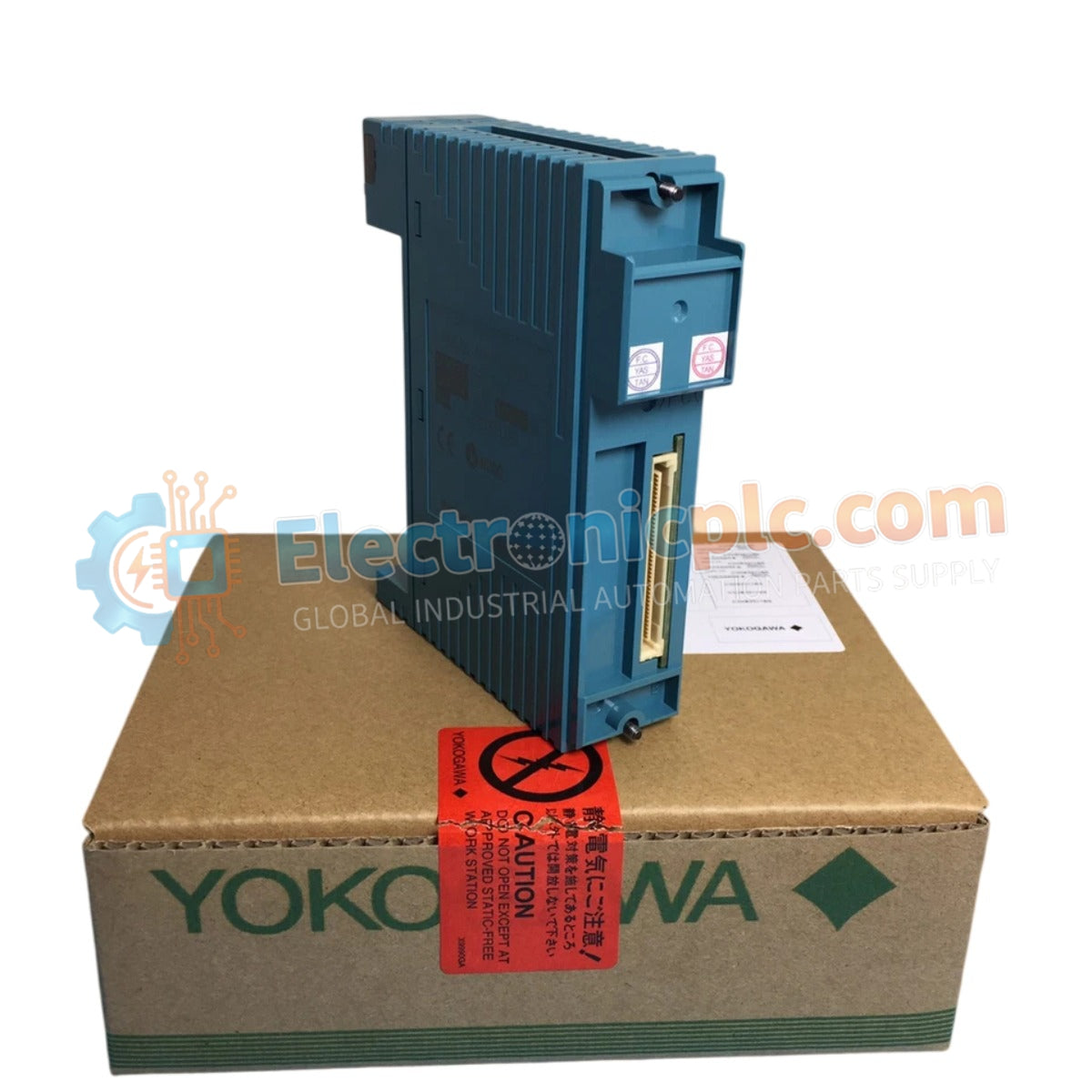
Configured for high-density 4-20 mA signal acquisition in CENTUM VP control networks, the Yokogawa NFAI135-S50/CCC01 (NFAI135-S50/CCC01 Analog Input Module) provides direct physical signal conditioning and digitalization of field-transmitted analog data.
...التوافر: الكمية المتبقية: 99
توصيل موثوق به في جميع أنحاء العالم
ضمان استرداد الأموال خلال 30 يومًا
هل تحتاج إلى مزيد من التفاصيل؟ اقرأ سياسة الشحن وسياسة الاسترداد الكاملة.


Configured for high-density 4-20 mA signal acquisition in CENTUM VP control networks, the Yokogawa NFAI135-S50/CCC01 (NFAI135-S50/CCC01 Analog Input Module) provides direct physical signal conditioning and digitalization of field-transmitted analog data.
| Parameter | Specification |
|---|---|
| Model | NFAI135-S50/CCC01 |
| Brand | Yokogawa |
| Origin | Japan |
| Weight | 0.3 kg |
| Dimensions | Standard I/O module form factor |
| Operating Temp | -20 deg C to 70 deg C |
| Power Consumption | Backplane powered (5 VDC/24 VDC) |
| Input Channels | 16 channels |
| Signal Input | 4-20 mA |
The NFAI135-S50/CCC01 utilizes galvanic isolation per channel to decouple field-side loops from the module internal backplane, effectively suppressing ground loops in dispersed instrumentation arrays. The module supports the 4-20 mA HART loop protocol, allowing for simultaneous process variable measurement and secondary digital device data acquisition. This dual-path processing ensures that HART communication does not interrupt the primary control loop integrity.
Q: Can the NFAI135-S50/CCC01 be used for non-HART analog inputs?
A: Yes, the module is backward compatible with standard 4-20 mA instrumentation. The HART communication logic is transparent to the primary analog input processing, provided that field devices are wired correctly to the module input terminals.
Q: How does the CCC01 conformal coating affect thermal dissipation?
A: The CCC01 conformal coating is applied to the PCB assembly to protect against corrosive environments and moisture. It has a negligible impact on the module's thermal dissipation characteristics when operated within the specified -20 deg C to 70 deg C temperature range.


