سلة التسوق الخاصة بي
0 عنصرًا
قطع غيار أصلية للأتمتة | توصيل سريع عالمي | ضمان لمدة 12 شهرًا — [احصل على عرض سعر]

The YOKOGAWA NFAI841-S00 S2, also cataloged as the NFAI841 Analog Input Module, operates as a dedicated hardware component for multi-range analog signal acquisition within CENTUM CS 3000 distributed control system...
التوافر: في الأوراق المالية
توصيل موثوق به في جميع أنحاء العالم
ضمان استرداد الأموال خلال 30 يومًا
هل تحتاج إلى مزيد من التفاصيل؟ اقرأ سياسة الشحن وسياسة الاسترداد الكاملة.

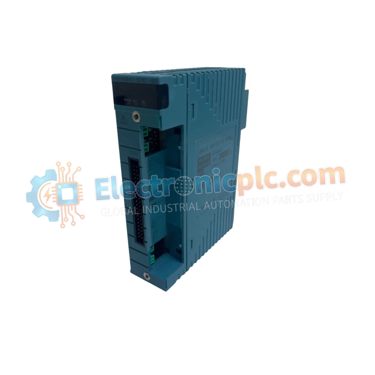
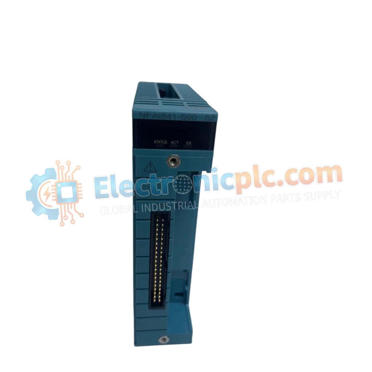
The YOKOGAWA NFAI841-S00 S2, also cataloged as the NFAI841 Analog Input Module, operates as a dedicated hardware component for multi-range analog signal acquisition within CENTUM CS 3000 distributed control system (DCS) architectures.
The NFAI841-S00 S2 utilizes a standardized suffix configuration for hardware version control. The -S00 designator identifies the module as a base configuration high-density input unit, while the S2 suffix signifies the second hardware iteration, ensuring compatibility with updated system backplane communication protocols and electromagnetic compliance standards.
| Parameter | Specification |
|---|---|
| Model | NFAI841-S00 S2 |
| Brand | YOKOGAWA |
| Origin | Japan |
| Weight | 0.35kg |
| Dimensions | 110 mm x 35 mm x 100 mm |
| Operating Temp | -20 deg C to 60 deg C |
| Power Consumption | 2.5 W |
| Input Channels | 8 |
| Input Signal Range | +/- 10 V, 0 to 20 mA |
| Input Impedance | 10 M Ohm |
| A/D Conversion | 16-bit |
| Sampling Rate | 50 Hz |
The NFAI841-S00 S2 is engineered to process both voltage and current inputs with high precision. In DCS environments, the module's high input impedance of 10 M Ohm for voltage signals minimizes loading effects on field instrumentation. To maintain signal integrity, proper shielding and grounding are required to mitigate common-mode noise, especially when integrating the module into control loops that utilize the 4-20 mA standard or bipolar voltage signals.
Q: Does the NFAI841-S00 S2 support hot-swapping?
A: The module is designed for standard DCS rack integration. Hot-swapping is generally supported provided the DCS system configuration is updated to handle module removal or insertion; however, operators must confirm system-specific power-up sequences to prevent bus communication disruptions.
Q: Can this module measure 4-20 mA signals directly?
A: Yes. The 0 to 20 mA input range is designed to accommodate standard 4-20 mA process signals. The module provides 16-bit resolution, allowing for high-precision digital representation of the measured current loop.


