سلة التسوق الخاصة بي
0 عنصرًا
قطع غيار أصلية للأتمتة | توصيل سريع عالمي | ضمان لمدة 12 شهرًا — [احصل على عرض سعر]

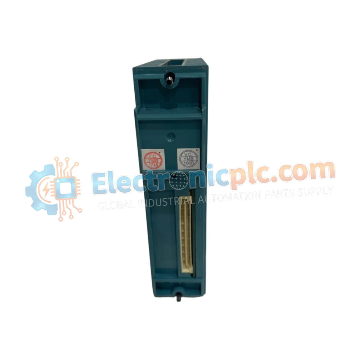
Configured for high-density digital signal acquisition in STARDOM control networks, the Yokogawa NFDV151-P10/CCC01 (NFDV151-P10 Digital Input Module) provides direct electrical execution of 32-channel isolated logic status monitoring.
التوافر: الكمية المتبقية: 99
توصيل موثوق به في جميع أنحاء العالم
ضمان استرداد الأموال خلال 30 يومًا
هل تحتاج إلى مزيد من التفاصيل؟ اقرأ سياسة الشحن وسياسة الاسترداد الكاملة.


Configured for high-density digital signal acquisition in STARDOM control networks, the Yokogawa NFDV151-P10/CCC01 (NFDV151-P10 Digital Input Module) provides direct electrical execution of 32-channel isolated logic status monitoring.
| Parameter | Specification |
|---|---|
| Model | NFDV151-P10/CCC01 |
| Brand | Yokogawa |
| Origin | Japan |
| Weight | 0.3 kg |
| Dimensions | Standard FCN/STARDOM module housing |
| Operating Temp | 0 deg C to +40 deg C |
| Power Consumption | 500 mA at 5 VDC |
| Input Channels | 32 isolated (sink/source compatible) |
| Rated Input Voltage | 24 VDC |
| Isolation Voltage | 2 kV AC (input to system) |
| Input Response Time | <= 8 ms |
The module utilizes galvanic isolation to provide 2 kV AC protection between input field signals and the internal system backplane. This architecture prevents common-mode noise and ground-loop currents from propagating into the FCN autonomous controller. Integrated surge protection is implemented on each of the 32 channels, providing voltage transient suppression for field instrumentation. The circuitry supports deterministic input detection with a max cycle of 25 Hz for pushbutton inputs, ensuring data consistency for time-sensitive logic execution.
Q: Is this module capable of handling both sink and source input configurations?
A: Yes, the NFDV151-P10/CCC01 is engineered to support both sink and source input types, offering flexibility for different field device wiring standards without requiring hardware modifications.
Q: What is the insulation rating between the channel common groups?
A: The module provides an isolation voltage of 500 V AC between common segments, which are grouped every 16 channels to maintain segmentation integrity.


