سلة التسوق الخاصة بي
0 عنصرًا
قطع غيار أصلية للأتمتة | توصيل سريع عالمي | ضمان لمدة 12 شهرًا — [احصل على عرض سعر]

Configured for high-density discrete signal control in STARDOM autonomous controller platforms, the Yokogawa NFDV551-P10/CCC01 (NFDV551 Digital Output Module) provides direct physical/electrical execution of 32-channel sink-type isolated transistor output switching.
التوافر: في الأوراق المالية
توصيل موثوق به في جميع أنحاء العالم
ضمان استرداد الأموال خلال 30 يومًا
هل تحتاج إلى مزيد من التفاصيل؟ اقرأ سياسة الشحن وسياسة الاسترداد الكاملة.

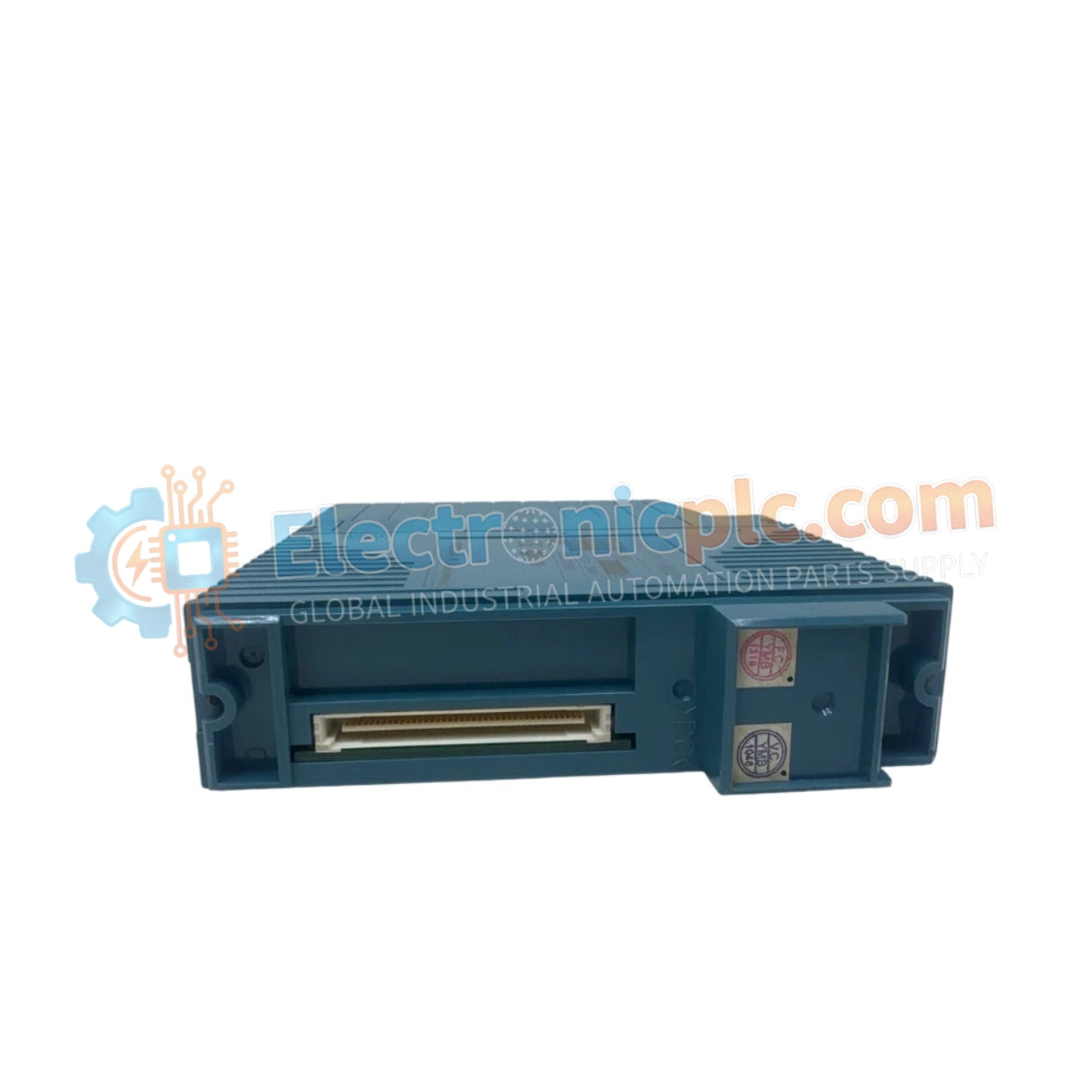
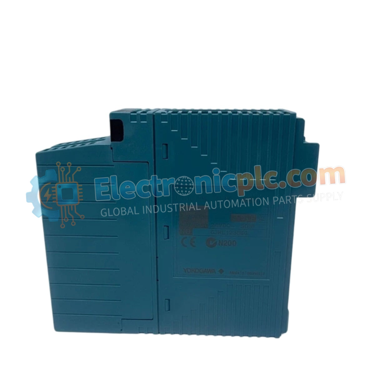
Configured for high-density discrete signal control in STARDOM autonomous controller platforms, the Yokogawa NFDV551-P10/CCC01 (NFDV551 Digital Output Module) provides direct physical/electrical execution of 32-channel sink-type isolated transistor output switching.
| Suffix | Specification |
|---|---|
| NFDV551-P10 | Base model with 32-channel digital output |
| /CCC01 | Integrated MIL connector cover for cable protection |
| Parameter | Specification |
|---|---|
| Model | NFDV551-P10/CCC01 |
| Brand | Yokogawa |
| Origin | Japan |
| Weight | 0.3kg |
| Dimensions | Standard STARDOM module footprint |
| Operating Temp | Not specified |
| Power Consumption | 700 mA @ 5 VDC |
| Output Channels | 32 (sink-type transistor) |
| Max Load Current | 100 mA per channel @ 26.4 VDC |
| Output Response Time | <= 3 ms |
The NFDV551-P10/CCC01 facilitates seamless integration with FCN, FCN-500, FCN-100, FCN-RTU, and FCJ autonomous controllers. The module employs channel-to-system isolation rated at 2000 VAC for 1 minute and inter-common isolation rated at 500 VAC for 1 minute. To ensure consistent signal integrity, the module supports configurable fallback modes (HOLD, OFF, or NO), allowing for defined safety states upon controller fault or loss of backplane communication. When driving inductive loads such as solenoids or relay coils, users must verify that surge suppression devices are installed to protect the transistor output stages from flyback voltage spikes.
Q: Can the module be configured for hot-swapping within the controller rack?
A: Operation and maintenance must adhere to the specific STARDOM rack power protocols. Always de-energize the local rack segment before module extraction to prevent backplane bus transients or pin-level arcing.
Q: How is the load voltage range constrained?
A: The operating voltage is strictly limited to 20.4 VDC to 26.4 VDC. Supplying voltage outside this range can compromise the switching reliability of the transistor outputs or lead to thermal degradation of the internal driver circuits.


