سلة التسوق الخاصة بي
0 عنصرًا
قطع غيار أصلية للأتمتة | توصيل سريع عالمي | ضمان لمدة 12 شهرًا — [احصل على عرض سعر]

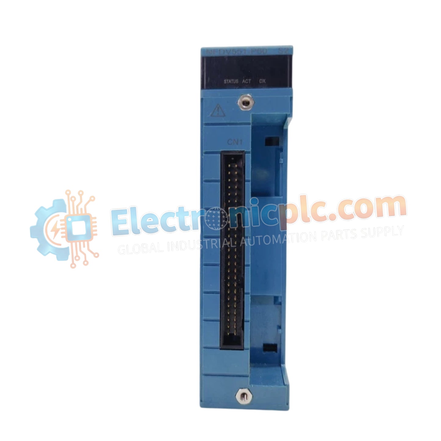
تعمل وحدة YOKOGAWA NFDV551-P60/D5S00، والمصنفة أيضًا كوحدة الإخراج الرقمي NFDV551، كمكون مادي مخصص لتنفيذ الإشارات المنفصلة ضمن منصات شبكة STARDOM.
| المعلمة | المواصفات |
|---|
| المعلمة | المواصفات |
|---|---|
| النموذج | NFDV551-P60/D5S00 |
| العلامة التجارية | YOKOGAWA |
| المنشأ | اليابان |
| الوزن | 0.3 كجم |
| الأبعاد | عامل شكل وحدة الإدخال/الإخراج القياسي STARDOM |
| درجة حرارة التشغيل | -40 درجة مئوية إلى 80 درجة مئوية |
| استهلاك الطاقة | 3 واط |
| قنوات الإخراج | 32 |
| الجهد المطبق المقدر | 24 فولت تيار مستمر |
| جهد الحمل | 24 فولت تيار مستمر، 50 مللي أمبير |
| معدل التحديث | 1 مللي ثانية لكل قناة |
تدمج وحدة NFDV551-P60/D5S00 العزل الجلفاني لفصل دوائر الحمل على جانب الحقل عن منطق اللوحة الخلفية الداخلية. يمنع هذا الهيكل العازل الضوضاء الكهربائية من المحركات أو المرحلات أو الصمامات المتصلة من الانتشار مرة أخرى إلى ناقل وحدة التحكم STARDOM. تم تصميم الوحدة للتنفيذ الحتمي لحالات الأمان من الفشل، مما يضمن في حالة فقدان اتصال وحدة التحكم أو وجود خطأ داخلي، أن تنتقل قنوات الإخراج إلى حالة محددة مسبقًا لمنع تجاوزات العملية.
س: هل تدعم هذه الوحدة التبديل السريع تحت الحمل؟
ج: يُسمح بالتبديل السريع فقط عندما يتم فصل طاقة حلقة الحقل. قد يؤدي محاولة إزالة أو إدخال الوحدة بينما يكون جهد الحمل 24 فولت تيار مستمر نشطًا إلى حدوث قوس كهربائي على دبابيس الموصل، مما يؤدي إلى تدهور مبكر للتلامس.
س: ما هو أقصى متطلبات قمع الحمل الاستقرائي للصمامات المتصلة؟
ج: يجب تركيب صمامات ثنائية خارجية للطيران العكسي أو أجهزة قمع الاندفاع عبر الأحمال الاستقرائية (مثل صمامات الملف اللولبي) لمنع تجاوز الفولتية الارتدادية الاستقرائية للجهد الناتج المقدر 24 فولت تيار مستمر للوحدة.